SIS Mixers
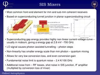
Most common front-end element for mm and sub-mm coherent receivers Based on superconducting tunnel junction in planar superconducting circuit Superconducting gap energy provides highly non-linear current-voltage curve – usually in niobium, giving a energy gap at 2.8 mV ~700 GHz

SIS Mixers
E N D
Presentation Transcript
Most common front-end element for mm and sub-mm coherent receivers Based on superconducting tunnel junction in planar superconducting circuit Superconducting gap energy provides highly non-linear current-voltage curve – usually in niobium, giving a energy gap at 2.8 mV ~700 GHz LO signal causes photon assisted tunnelling – photon steps Non-linearity has smaller energy scale than mm photon – quantum mixing Allows for very low conversion loss, and even conversion gain Fundamental noise limit is quantum noise – 2.4 K/100 GHz Additional noise from – RF losses, shot noise in SIS junction, IF amplifier (multiplied by conversion loss of mixer) SIS Mixers
Need good coupling from signal to very small SIS device (~1 micron square) Most mm-wave mixers are waveguide devices – quasi-optical coupling used at sub-mm and >1 THz Coupling from waveguide to planar circuit via waveguide probes or finlines Planar circuit also contains tuning circuit to tune out capacitance of junction IF signal (typically few GHz) from mixer coupled out via bias tee to LNA IF low noise amplifier is usually as separate module – although now starting to be integrated into mixer block SIS Mixers
Major programs in SIS mixers have been aimed at ALMA and Herschel HIFI SIS mixers also used on – JCMT, CSO, SMA, etc. and in atmospheric science Typical IF bands – 4-6 GHz (JCMT, SMA), 4-8 GHz (HIFI), 4-12 GHz (ALMA) State of the art - sensitivity HIFI SIS Mixers as delivered
Receiver architectures in use at mm frequencies: Waveguide and on-chip LO coupling injection (Chalmers, many others) Waveguide side-band separating mixers (ALMA, IRAM, many others) Dual polarisation mixers (Waveguide OMTs (ALMA), quasi-optical (ALMA, HIFI)) Balanced mixers (Waveguide and single chip designs) Imaging arrays currently in development/commissioning (not complete list!): 16 pixel HARP-B (350 GHz) – commissioning/operational on JCMT 9 pixel HERA (230 GHz) –operational on IRAM 30m – 49 pixel Super HERA under development plus 150 GHz array with photonic LO 64 pixel SuperCAM (350 GHz) – in development at Arizona for SMT State of the art - receivers IRAM Chalmers
SIS mixer advantages Coherent Spectral resolution Phase switching via LO signal (or mixer bias?) Correlation/pseudo-correlation of IF signal post-amplification – allows interferometry on large numbers of baselines 4 K cryogenics SIS mixer disadvantages IF bandwidth – limited by LNAs, mixer design and IF processing LO distribution – particularly in imaging arrays Need magnetic field at junction to suppress Josephson currents SIS Mixers for CMB/SZ
Possible applications: S-Z imaging/spectral interferometer – See GUBBINS talk later Can get moderate spectral resolution with analogue backends Using both sidebands can give differential measurement across null frequency Polarimetric interferometry Dual polarization mixers, wide bandwidth correlators Mm-wave phase switched pseudo-correlation polarimeter Could build on current imaging array developments SIS Mixers for CMB/SZ
Mixer developments required to overcome disadvantages: IF bandwidth: Design tuning circuits, IF outputs for wide IF – relies heavily on CAD software (HFSS, Sonnet, CST, SuperMix) Tight integration with LNAs – reduce parasitics, no need to go via 50 Ohm coax, could include LNA matching on superconducting circuit IF LNA and backend processing bandwidth needs development LO distribution: On-chip/in-block LO coupling – cleaner optics, reduced LO power requirements (particularly in balanced mixers) Photonic LOs – cryogenic module fed by optical fibre close to mixer chip Magnetic field control (particularly for imaging arrays): Smaller magnets to adjust field close to chip On chip magnetic field generation for tweaking local fields SIS Mixers for CMB/SZ
Wide IF band mixers (>20 GHz) at 230 GHz New mixer design on silicon – easier fabrication Step towards SOI techniques for easier integration Gives very thin silicon substrates (0.5->15 micron) Allows beamlead techniques for chip grounding and IF connection Suitable for use with Planar OMT designs SIS mixers at 700 GHz On-chip LO injection and sideband-separation Photonic LO for 230 GHz and eventually 700 GHz SIS Development at Oxford UVa/Arizona
GUBBINS – Single baseline 220 GHz interferometer prototype for S-Z 0.5m baseline, 0.4 m antennas feeding SIS mixers with 20 GHz IF bandwidth LO tunable from 195-260 GHz 2-20 GHz analogue correlator – sideband separating, 16 frequency channels per sideband Initial mixer chips use finline single-ended mixers with RF-bandpass filter to prevent IF leaking into finline - LO directional coupler in mixer block IF transformer to convert 20 Ohm mixer output to 50 Ohm required by LNAs First batch of chip being tested – problem with RF bandpass filter, will be resolved on next batch Next generation chip design using 50 Ohm characteristic impedance and new unilateral finline – eventually test balanced and sideband–separating mixers GUBBINS mixers
Photonic Local Oscillators - Mix two 1.5 um lasers with mm-wave difference frequency Uses commercially available photodiodes – LO distribution via optical fibre Mm-wave signal generated close to mixer – can operate at cryogenic temps Oxford have joint student (Boon Kok Tan) with RAL MMT group (Peter Huggard) developing photonic LO RAL LOs used on IRAM 150 GHz SIS array (Room temp LO, inside cryostat) Oxford SIS mixer pumped with RAL LO at 230 GHz (optimised for 150 GHz) Supporting technologies Position of optical fibre. Photodiode chip Single piece filter/ probe
Planar OMTs - Four probes into circular waveguide on Si or SiN membrane Direct coupling onto detector chip (or to coax at low frequencies) Compact, simple to make, trivial waveguide machining Extremely high performance - -50-70 dB isolation over >40% bandwidth Smooth wall horns – Uses number of discontinuities to generate corrugated horn-like beam pattern Can be made by direct drilling up to and above 230 GHz Can make very cheap arrays Supporting technologies