Mixers
Mixers. An Introduction. Mixers: Overview.

Mixers
E N D
Presentation Transcript
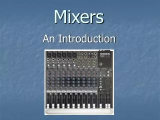
Mixers An Introduction
Mixers: Overview • A mixer is a device that is able to accept signals from a wide variety of sources and then alter them in some way by changing their level, equalization and effects. The signals are then routed to output connections. This is most often to a pair of tracks (left and right), however most mixers present several options. • Mixers take many forms from simple to extremely complex.
Mixers: Applications • Mixers are used in a wide variety of situations. • These include: live concerts, public address systems, recording studios, radio stations, DJs, television studios and film shoots.
A mixer is divided into four main sections: • Input Connections • Channel Strip • Master Section • Output Connections
Input Connections • This is the part of the mixer where the different sound sources are plugged in. These may include: microphones, direct boxes, guitars, keyboards, CD players and turntables. • This is also the section of the mixer where effects devices are patched in. Examples include: compressors, reverb, chorus or delay.
A B C D A (XLR MICROPHONE INPUTS): Low impedance (resistance) , balanced microphone XLR input that can also provide phantom power to a condenser microphone Pin 1 : ground or shield Pin 2 : Positive (+ or hot) Pin 3 : Negative (- or cold) B (1/4’’ LINE INPUTS): 1/4’’ input that can accept two different connections. i) unbalanced/high impedance/TS (TIP/SLEEVE) connectors ii) balanced/low impedance/TRS (TIP/RING/SLEEVE) connectors C (LOW CUT switch): Cuts bass frequencies below 75Hz at a rate of 18dB per octave D (TRIM): Adjusts the input sensitivity of the mic and line inputs. i) XLR input can be boosted by 60 dB ii) LINE input can be attenuated (brought down) by 15dB or boosted by 45 dB. “U” is when there is no gain or attenuation to the signal
F G E E (STEREO LINE INPUTS): Fully balanced inputs that are used for stereo or mono, balanced or unbalanced signals. These are often used to hook up stereo signals from keyboards, tape/CD/MP3 players and sometimes effects devices. Odd channel = LEFT and Even channel =right. F (AUX EFFECTS SEND/RETURNS) : Used to connects the inputs and outputs of effects devices (reverb/delay/compressor/chorus etc..) AUX 1 can be used for stereo or mono effect AUX 2 can only be used for stereo effects There is also an option of using the SEND Outputs on either AUX to feed the signal to monitors instead of effects. G (UNBALANCED RCA TAPE/CD/MP3 PLAYER INPUTS/OUTPUTS): Used to hook up most types of audio players/recorders except for turntables. The input signal is automatically boosted by 6 dB. The output line is used for making a stereo recording (board mix) from the mixer’s main outputs.
H I H (1/4” MAIN OUTPUTS): This is one of Two Main Stereo Outputs. Either unbalanced (TS) or balanced (TRS) 1/4’’ connectors can be used. TIP (T): + (hot) RING (R): - (cold) SLEEVE (S): Ground I (PHONES OUTPUT): Used for listening to mixer’s output with stereo headphones with 1/4’’ (TRS) output.
Channel Strip • This is the section of the mixer where basic adjusts are made to the incoming signal such as: effect level, equalization, panning, signal routing, and volume level. • Most channel strips are used for an individual microphone or a mono instrument line. Some channel strips will accept stereo signals. Usually those on the far right of the console.
AUX : Used to set the amount of signal that is sent to an external processor or to monitors. 3 Band Parametric EQ : Hi : Boost or cut frequencies around 12000 Hz (12kHz) by 15dB MID : Boost or cut frequencies around 2500 Hz (2.5kHz) by 12dB LOW : Boost or cut frequencies around 80 Hz by 15dB PAN : Adjusts the amount of channel signal sent to the left vs. right outputs. Dual purpose MUTE/ALT 3-4 Switch: Will silence the channel or send the signal from this channel to the ALT 3-4 bus. SOLO switch: Silences all other channels except for this one. CHANNEL FADER : Controls the channel level from Unity Gain (U) up to 10 dB of boost or down to oo
Master Section This is the control centre of the mixing board. • level adjustments are made: effects, stereo output (L/R), ctr room/submix outputs (L/R). • meters and lights indicate: mixer power, phantom power, rude solo light, VU meters. • signal routing options are chosen: pre/post efx, efx to monitors, control room/submix signal source.
J ( AUX 1 MASTER) : Provides overall control of signal that is sent from the AUX SEND 1 output. AUX SEND 2 has no output dial ! K (EFX TO MONITOR) : Used to send EFX from AUX SEND 2 into AUX SEND 1. L (AUX RETURNS): Sets the amount of effect coming in from the AUX RETURNS 1 and 2 M (AUX 1 SELECT) : Allows you to choose whether you want to tap the signal that is to be effected either PRE-FADER/UP (most common when used for monitoring) or POST-FADER/DOWN (usually only used for effects when you want the “wet” signal to follow the “dry” signal). N (CONTROL ROOM/SUBMIX MATRIX): Buttons that allow the engineer to quickly route the MAIN MIX, ALT 3-4 selected channels, or the TAPE INPUTS to the Control Room/SubMix/Phones Outputs. Any combination of these may be chosen simultaneously. O (ASSIGN TO MAIN MIX): Feeds the C-R/SOURCE Selections into the MAIN MIX. P (SOLO MODE) : This is used to set Pre-Fader Listen (PFL) and After-Fader Listen (AFL) levels on the VU Meters J K L M N O P
Q (PHANTOM POWER AND MIXING BOARD POWER LIGHTS): Allows the engineer to know when phantom power or the mixer is itself is turn on. R (VU METERS): Displays volume units for specific signals that are chosen in the C-R/SOURCE matrix or soloed channels. S (CONTROL ROOM/SUBMIX): Sets master level of CONTROL ROOM/SUBMIX T (MAIN MIX): Sets overall level of the MAIN MIX U (RUDE SOLO LIGHT): This light reminds the engineer if any of the channels are in solo mode. R Q U S T
Output Section • This is the portion of the mixer where different cables are patched in to feed the signal to other sources. This could be: power amplifiers, speakers, recording devices, effects, headphones or other mixers.
V W X Y V (POWER CONNECTION and FUSE BOX): Internal power supply that powers the mixer. Accepts a standard 3 prong IEC power cord. Below is a compartment that houses a 0.5 amp fuse. W (POWER SWITCH) : Turns mixer power on and off. X (PHANTOM POWER SWITCH) : Turns phantom power for condenser microphones on and off. Y (XLR MAIN OUTPUTS): Left and Right XLR/low impedance/ Balanced Output that are controlled by the MAIN MIX fader.
Z AA BB CC Z (MAIN OUTPUT LEVEL PAD): Lowers the signal level from the MAIN OUTPUTS by 30 dB. This is helpful when feeding the main mixer signal to another mixer. AA (1/4 ‘’ CONTROL ROOM OUTPUTS): Balanced or unbalanced 1/4’’ output whose level is controlled by the CONTROL ROOM/SUBMIX fader. BB (1/4 ‘’ ALT OUTPUT): Balanced or unbalanced 1/4’’ output for any channels where the MUTE ALT 3-4 button is selected. CC (CHANNEL INSERTS): Allows certain effects to be connected to single channels using a TRS Insert Cable . This is used most often for compressors, filters, equalizers and de-essers.