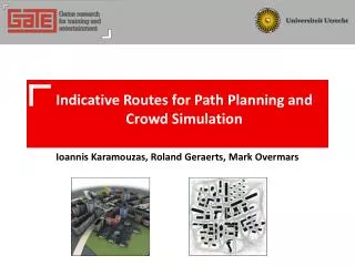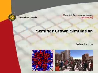
Roland Geraerts Seminar Crowd Simulation 2011
470 likes | 660 Vues
Path Planning with Explicit Corridor Maps Related work Constructing Explicit Corridor Maps Corridor Map Method Exploiting Explicit Corridors. Roland Geraerts Seminar Crowd Simulation 2011. Related work: A*. Method Construction phase: create a grid, mark free/blocked cells

Roland Geraerts Seminar Crowd Simulation 2011
E N D
Presentation Transcript
Path Planning with Explicit Corridor Maps Related work Constructing Explicit Corridor Maps Corridor Map Method Exploiting Explicit Corridors Roland Geraerts Seminar Crowd Simulation 2011
Related work: A* • Method • Construction phase: create a grid, mark free/blocked cells • Query phase: use A* to find the shortest path (in the grid) • Advantage • Simple • Disadvantages • Too slow in large scenes • Ugly paths • Little clearance to obstacles • Unnatural motions (sharp turns) • Fixed paths • Predictable motions
Related work: Potential Fields • Method • Goal generates attractive force • Obstacles generate repulsive force • Follow the direction of steepest descent of the potential toward the goal • Advantages • Flexibility to avoid local hazards • Smooth paths • Disadvantages • Expensive for multiple goals • Local minima
Related work: Probabilistic Roadmap Method • Method • Construction phase: build the roadmap • Query phase: query the roadmap • Advantages • Reasonably fast • High-dimensional problems • Disadvantages • Ugly paths • Fixed paths • Predictable motions • Lacks flexibility when environment changes
Related work: Probabilistic Roadmap Method • Method • Construction phase: build the roadmap • Query phase: query the roadmap • Advantages • Reasonably fast • High-dimensional problems • Disadvantages • Ugly paths • Fixed paths • Predictable motions • Lacks flexibility when environment changes
State-of-the-art: Navigation meshes • Method • Create a representation of the "walkable areas" of an environment • Extract the path • Advantages • General approach • Construction is fast due to use of GPU • Examples and source code can be found on http://code.google.com/p/recastnavigation • Disadvantages • Often needs a lot of manual editing • Current techniques are imprecise • Bad support for non-planar surfaces Obstacles Walkable voxels Voxel regions Polygonal regions Convex regions A path
State-of-the-art: Navigation meshes • Some open problems • Automatic annotation of the map • Areas: walk, climb, jump, crouch, “avoid” … • Special places: hiding and sniper spots, … • Handle large (dynamic) changes • Efficiently updating the data structure and paths • Improve the efficiency of mesh generation (large scenes) • Wrong coverage/connectivity due to confusing elements • Steep stairs, ramps, hills, curved surfaces, gaps • The mesh is only a data structure storing the walkable areas • How to create visually convincing paths?
Towards a new methodology: Requirements • Fast and flexible path planner • Real-time planning for thousands of characters • Dealing with local hazards • Global path • Natural paths • Smooth • Short • Keeps some distance toobstacles • Avoids other characters • … Titan Quest: Immortal throne
Capturing the free space • Requirements of the data structure representing the free (walkable) space • Existence of a path • Contains all cycles • Short global paths, alternative paths • Provides high-clearance paths (corridors) • Provides maximum local flexibility • Small size • Fast extraction of paths • A good candidate • Generalized Voronoi Diagram + annotation
Voronoi Diagram • Some inspiration from natural objects… maple leaf drying mud bacteria colonies wasps nest giraffe
Voronoi Diagram • Definitions • Voronoi region: set of all points closest to a given point • Voronoi diagram: union of all Voronoi regions Voronoi sites: (red) points
Voronoi Diagram • Approximation of the Voronoi Diagram • Compute a distance mesh for each point • Render each mesh in a different color by using the GPU • Using the Z-buffer, only pixels with the lowest distance values attribute to a pixel in the Frame buffer • A parallel projection of the meshes gives the diagram Perspective view (Z-buffer) Top view (Frame buffer)
Generalized Voronoi Diagram • Generalized Voronoi Diagram supports any type of obstacles • Point, disk, line, polygon, … • Convert concave polygons into convex ones, otherwise edges do not run into all corners
Generalized Voronoi Diagram • Generalized Voronoi Diagram supports any type of obstacles • Point, disk, line, polygon, … • Convert concave polygons into convex ones, otherwise edges do not run into all corners • Distance meshes • Point: cone • Disk: lifted cone • Line: tent + 2 cones • Polygon: n (point + line meshes) • Literature • [Hoff et al., 1999] • [Geraerts and Overmars, 2010]
From GDV to Medial axis • Generalized Voronoi Diagram (GVD) • Render distance meshes for each obstacle • Boundaries: bisectors between any two closest obstacles • Medial axis • Yields bisectors between any two distinct closest obstacles • Extraction of the medial axis • Edge: trace pixels between Voronoi regions; continue tracingwhen closest points on the obstacles are equal • Vertex: end point of an edge Medial axis GVD
Medial axis • The good • Existence of a path: full coverage/connectivity • Contains all cycles: yes • Provides high-clearance paths: yes • Small size: yes (linear) • Fast extraction of paths: yes • The bad • Unclear how to extract short(est) paths • Moving along 1D-curves limits flexibility • The ugly • Deal with robustness
Explicit Corridor Map • Basis: Medial Axis • Plus: annotated event points on the edges • Points where the type of bisector on the edge changes • Straight lines versus parabola’s (bisector of point and line) • Changes occur at crossing between site normal and edge • Annotation: its two closest points on the sites • Equals: planar subdivision (or navigation mesh) • Memory footprint The storage is linear in the number of obstacle vertices. • NoteThere is no need for storing pixels.
Explicit Corridor Map: closest points • Computation of the closest points • Look up incident colors at the event point’s position • Each color was linked to an unique obstacle • Compute the (left and right) closest points to each obstacle using simple linear algebra
Explicit Corridor Map: experiments • Performance • Setup • NVIDIA GeForce 8800 GTX graphics card • Intel Core2 Quad CPU 2.4 GHz, 1 CPU used • Experiments • McKenna: 200x200 meter, 1600x1600 pixels, 23 convex polygons
Explicit Corridor Map: experiments • Performance • Setup • NVIDIA GeForce 8800 GTX graphics card • Intel Core2 Quad CPU 2.4 GHz, 1 CPU used • Experiments • McKenna: 200x200 meter, 1600x1600 pixels, 23 convex polygons time: 0.03s
Explicit Corridor Map: experiments • Performance • Setup • NVIDIA GeForce 8800 GTX graphics card • Intel Core2 Quad CPU 2.4 GHz, 1 CPU used • Experiments • City: 500x500 meter, 4000x4000 pixels, 548 convex polygons
Explicit Corridor Map: experiments • Performance • Setup • NVIDIA GeForce 8800 GTX graphics card • Intel Core2 Quad CPU 2.4 GHz, 1 CPU used • Experiments • City: 500x500 meter, 4000x4000 pixels, 548 convex polygons time: 0.3s
Explicit Corridor Map: experiments • Supports large environments • E.g. 1 km2 • Millimeter precision • However, there must be at leasttwo pixels in between two obstacles to discover an edge
Explicit Corridor Map: recent work • Extension to 2.5D (multi-layered) environments • Technique • Result (46 ms) Updated medial axes for Li and Lj Connection scene Multi-layered environment Partial medial axes for Li and Lj
Explicit Corridor Map: recent work • Handling dynamic changes • Technique for adding a point/line • Result (1 – 2.7 ms per update) A Finding closest site Continue in 1 dir. w1 has been reached Updated VD (point) Updated VD (line)
Compare with the old approach • Disadvantages Implicit Corridor Map • More than linear storage (due to discrete sample points) • Non-exact representation • Additional parameters requiredfor local sampling density
Explicit Corridor Map: some thoughts • Open questions • Can we make a dynamic version of the ECM? • Dimensionality • Can we generalize the ECM data structure to 2.5D? • How should we add height information? • How can we handle these extensions? • Terrains (elevation) • Different topological spaces • Different terrain types (grass, road, pavement) • How should we handle holes and enable jumping? Examples of different topological spaces (plane, sphere, cylinder, torus, Möbius strip, Klein bottle)
The Corridor Map Method • Construction phase (offline) • Build Explicit Corridor Map • Build kd-tree that stores the ECM • Query phase (on-line) • Construct indicative route • CMM: Medial axis
The Corridor Map Method • Query phase (on-line) • Construct indicative route • CMM: Medial axis • Compute a corridor • Compute a path • Construction phase (offline) • Build Explicit Corridor Map • Build kd-tree that stores the ECM • Distinguish three scales1. Macro (corridor)2.Meso (indicative route)3. Micro (local behavior)
The Corridor Map Method • Query phase (on-line) • Retract the start and goal to the medial axis • Query the kd-tree • Connect the start and goal to the Corridor Map • Compute the shortest backbone path (using A*) Explicit Corridor Map Query Corridor with its backbone path
The Corridor Map Method • Query phase (on-line) • Compute the path • While the corridor determines the character’s global path, forces determine its local path • The forceF(x)=Fa(x)+Fo(x) causes the character to accelerate, pulling it toward the goal. The variable x is the character’s position • Using Newton's Second Law, we have F = Ma, where M = mass = 1 and a = acceleration • Hence, the force F can be expressed as: • Combining these expressions gives us: A smooth path
goal α(x) x The Corridor Map Method • Query phase (on-line) • Compute the path: forces • The attraction force steers the character toward the goalFa(x) = , where f controls the magnitudea(x) =attraction point: the furthest point on the backbone path whose disk encloses the character. • Note on old approachThis is an discrete corridor instead of continuous explicit corridor.
R[t] goal α(x) d x The Corridor Map Method • Query phase (on-line) • Compute the path: forces • The boundary force keeps the character inside the corridorThis force is hidden inside the attraction force: (r=character’s radius) f=0, when the character is positioned at its attraction point (i.e. d=0)f=∞, when the character touches the disk’s boundary • Note on old approachThis is an discrete corridor instead of continuous explicit corridor.
The Corridor Map Method • Query phase (on-line) • Compute the path • Solving the equation gives us the character’s positions • Cannot be done analytically • revert to a numerical approximation A smooth path
The Corridor Map Method • Choice of forces • Combining these forces and using disks was a bad choice • This is solved by the IRM, which uses Explicit Corridors • Comparison of their vector fields Vector field: CMM force Vector field: IRM force
The Corridor Map Method: Examples • Query phase (on-line) • Compute the path: forces • Adding/changing forces leads to other “behavior” Smooth path Short path Obstacle avoidance Obstacle avoidance (Helbing model) + path variation = crowd? Coherent groups Path variation Camera path
The Corridor Map Method: Examples • Query phase (on-line) • Compute the path: forces • Adding/changing forces leads to other “behavior” Stealth-based path planning
Exploiting Explicit Corridors • The Corridor’s boundaries are given explicitly • Construction • Convenient representation • Small storage: linear in the number of samples (i.e. events) • Computation of closest points in O(1) time (on average) • Allows computing shortest minimum-clearance paths
Explicit Corridors: Obtaining clearance • Minimum clearance in explicit corridors • For each closest point cp, move cp toward its center point c • The displacement equals the desired clearance clmin • Insert event point(s) if clmin > distance(c, cp) c cp Explicit Corridor Shrunk corridors Shrinking a corridor
Explicit Corridors: Shortest paths • Computing the shortest path • Construct a triangulation • 2ith triangle: (li , ri , li+1) ; 2i+1th triangle: (ri , li+1 , ri+1) • If the start [goal] is not included, add triangle (s, l1 , r1) [(ln , rn ,g)] • Compute the shortest path • Funnel algorithm [Guibas et al. 1987] ri+1 li+1 g ri li s Triangulation Shortest path Explicit Corridor
Explicit Corridors: Shortest paths • Sketch of the Funnel algorithm • Funnel • Tail: computed shortest path from start to apex • Fan: 2 outward convex chains plus one diagonal • The fan keeps track of all possible shortest paths • Algorithm • Add diagonals iteratively whileupdating the funnel • Algorithm is linear in the number of diagonals • (or events) start tail apex fan diagonal goal
Explicit Corridors: Shortest paths • Computing the shortest minimum clearance path • Shrink the corridor • Construction time: linear in the number of event points • Compute the shortest path • Adjust Funnel algorithm to deal with circular arcs • Construction time: linear in the number of event points Left/right closest points Triangulation Shortest path
Improving the CMM: IRM • Compute a smooth path: Indicative Route Method • Compute the shortest minimum-clearance path • Define the attraction force • Pulls the character toward the goal • Define the boundary force • Keeps the character inside the corridor • Time-integrate the forces • Yields a smooth (C1-continous) path
The Query Phase: Experiments • Performance • Setup • Intel Core2 Quad CPU 2.4 GHz, 1 CPU • Experiments • City: 500x500 meter, 1.000 random queries • Results (average query time)
The Query Phase: Experiments • Performance • Setup • Intel Core2 Quad CPU 2.4 GHz, 1 CPU • Experiments • City: 500x500 meter, 1 query • Results (query time) • 2.8 ms ECM (0.3s) Explicit corridor Shrunk corridor Triangulation Shortest path Smooth path
Integration in Second Life • Implementation in Second Life Virtual World Bitmap Interface Camera path Path planning on server:http request
Conclusion • Advantages • Fast and flexible planner creates visually convincing paths • Computation of smooth, short minimum clearance paths • The algorithms run in linear time and are fast • The algorithms are simple • Open problems • Automatic annotation of the navigation mesh • Handling 3D spaces • Handling extensions • Handling character behavior • E.g. shopping and beach behavior • Interaction between different entities (human, car, bicycle)