Seeding with High Harmonics
Seeding with High Harmonics. Franz X. Kaertner Department of Electrical Engineering and Computer Science and Research Laboratory of Electronics, Massachusetts Institute of Technology, Cambridge, USA. Outline. I. Advantages of Seeding II. High-Harmonic Generation

Seeding with High Harmonics
E N D
Presentation Transcript
Seeding with High Harmonics • Franz X. Kaertner • Department of Electrical Engineering and Computer Science and • Research Laboratory of Electronics, • Massachusetts Institute of Technology, Cambridge, USA
Outline I. Advantages of Seeding II. High-Harmonic Generation III. Optimization of High-Harmonic Generation IV. Carrier-Envelope Phase Control V. Conclusion
SASE properties Time profile Time profile (log plot) Spectrum GINGER simulation of SASE FEL at 0.3 nm. For simulation speed. True bunch length will be longer. W.S. Graves, MIT Bates Laboratory
Seeding for narrow linewidth Spectrum Output time profile Time profile (log plot) GINGER simulation of seeded FEL at 0.3 nm. Same ebeam parameters as SASE case. W.S. Graves, MIT Bates Laboratory
Seeding for short pulse Output time profile Time profile (log plot) Spectrum GINGER simulation of seeded FEL at 0.3 nm. Same ebeam parameters as SASE case. W.S. Graves, MIT Bates Laboratory
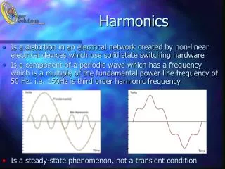
100 mJ - 1 mJ @ 800 nm XUV @ 3 – 30 nm h = 10-8 - 10-5 t Propagation Recombination 0 wXUV x tb -Wb Ionization Energy Laser electric field High-Harmonic Generation Noble Gas Jet (He, Ne, Ar, Kr) Cut-off Harmonic:
F = 0 Electric Field Time F = p/2 Sub-fs High-Harmonic Generation M. Hentschel, et al., Nature, 414, 509 (2001) A. Baltuska, et al., Nature, 421, 612 (2003) Highest wavelength emitted depends on carrier-envelope phase Single-Attosecond pulse (650 as) -> Stable seed energy is only possible with phase controlled laser source
Dependence of HHG on carrier-envelope phase • Atomic dipole moment depends on electric field • HHG depends on carrier-envelope phase, particularly near cutoff • Experiment: Laser intensity .7x1015 W/cm2, pulsewidth 5 fs, propagation of 2mm neon, for various carrier-envelope phases • Clear dependence of HHG near the cutoff harmonic on CEP • Discussion with H. C. Kapteyn: Also 20 fs driver pulses need carrier-envelope stababilization Ref. Brabec et al. … A. Baltuska, et al., Nature, 421, 612 (2003)
Published Results: Early pioneers: McPherson et al., J. Opt. Soc Am B4, 595 (1987) Ferry et al., J. Phys. B 21, 131 (1987) New results: Takahashi et al.: 16 mJ, 35 fs, @800nm 300 nJ @ ~30nm), Postdeadline Paper CLEO 2002 Schnürer et al.: Few-cycle pulse: 1mJ, 5 fs h =10-6,1 nJ@ ~30nm Phys. Rev. Lett. 83, 722-725 (1999) Bartels et al.: Shaped pulses: Nature 406, 164 (2000) improvement by a factor of 10 @ 30th harmonic H. C. Kapteyn h =10-4 - 10-5 @ 30th harmonic Quasi-Phase-Matching: Nature 421, 51 (2002) improvement by a factor of 7 @ 30th harmonic -> 1 0 nJ improvement by a factor of 100 @ 100th harmonic
High Harmonic Generation in Hollow Fibers Courtesy of M. Murnane and H. Kapteyn, JILA
Optimization of HHG Pulse shaping of drive laser can enhance a single harmonic Quasi-phase matching in modulated hollow-core waveguide. Courtesy of M. Murnane and H. Kapteyn, JILA How much improvement can we get with additional phase control for the very high harmonics in the water window < 4 nm ?
HHG has produced wavelengths from 50 nm to few nanometers, but power is very low for wavelengths shorter than ~10 nm. • Best power at 30 nm. • Improvements likely to yield 10 nJ at 8 nm. • Rapidly developing technology. HHG spectra for 3 different periodicities of modulated waveguides. Courtesy of M. Murnane and H. Kapteyn, JILA
Few-Cycle Pulse and HHG Generation In Photonic Bandgap Fiber (Y. Fink, RLE@MIT) Chalcogenide Glass Poly-Ether Sulfone (PES) Temelkuran et al., Wavelength-scalable hollow optical fibers with large photonic bandgaps …, Nature, 2002. 420: p. 1885-1886. • Truly guided modes (assuming infinite coating thickness, strong differentiation between different modes, large core fibers effectively in single mode • Modal Dispersion can be engineered for optimum pulse compression and/or phase and group velocity matching in HHG.
Dielectric Dielectric waveguide waveguide with uniform layers with uniform layers km) km) 20 20 - - /nm /nm 10 10 ps ps 0 0 Dispersion D ( Dispersion D ( Dielectric Dielectric waveguide waveguide - - 10 10 with defect with defect 1.2 1.2 1.4 1.6 1.8 2 2.2 - m m Vacuum wavelength ( ( m) m) Modification of Dispersion in PBG-Fibers Matching of group and phase velocities is possible
f CE Carrier-Envelope Phase Field Envelope Phase Controlled Laser Pulses Electric field of a 1.5-cycle optical pulse Maximum field depends on f CE L. Xu, et al., Opt. Lett. 21, 2008, (1996)
Optical Clocks SHG Spectrum ... ... ... Df - + Frequency Df 0 1 = Periodic Pulse Train with T R Df f f f o o o f CEO Carrier-Envelope Phase and Frequency Metrology T. Udem, et al., PRL 82, 3568 (1999) D. Jones, et al., Science288, 635-639 (2000) Provides an ultrastable modelocked pulse train! The clock of the Facility
1mm BaF2 Octave, Prismless Ti:sapphire Laser f = 10o Laser crystal: 2mm Ti:Al2O3 OC 1 PUMP L = 20 cm OC 2 BaF2 - wedges Base Length = 30cm for 82 MHz Laser
DCM-Pairs Covering One Octave Pump Window
Broadband, Prismless Ti:sapphire Laserand Carrier-Envelope Detection
Carrier-Envelope Beat Frequency Comb for Optical Metrology on Ultracold Hydrogen by Prof. Kleppner
High-Harmonic Seed Generation (CPA) 0.5 mJ A. Baltuska, et al., Nature, 421, 611 (2003)
High-Harmonic Seed Generation (P-CPA) Yb:YAG Amplifier 1ns, 20mJ, 1-10 kHz @1064 nm Q-switched Yb:YAG, 1ns, 1mJ 1-10 kHz 2nd-Harmonic 1ns, 10mJ, 1-10 kHz @ 532 nm 5fs, 5mJ 1-10 kHz GV-matched P-CPA with BBO Stret- cher Com- pressor Carrier-Envelope Stabilized Ti:Sapphire, 4 fs, 100MHz Phase Control
Conclusions • Stable HHG needs phase controlled high energy pulses (It has been shown to be possible) • Optimization of HHG results already to 10-5 efficiency at 30 nm • -> 10 nJ seed energies. • Photonic Band Gap fibers lead to novel opportunities for HHG generation because of novel opportunities for phase and group velocity matching • Laser technology is rapidly developing from CPA P-CPA