HVAC Smart Control Group 2
520 likes | 882 Vues
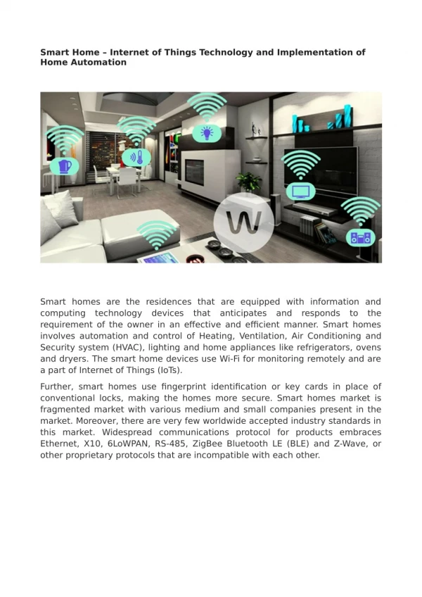
HVAC Smart Control Group 2. Steven Jones Jerthwin Prospere Matthew Arcuri Elroy Ashtian. HVAC. Heating Ventilation Air Conditioning. To provide a more energy efficient HVAC system, with enhanced user interface and over all more interactivity and control. Project Overview.

HVAC Smart Control Group 2
E N D
Presentation Transcript
HVAC Smart ControlGroup 2 Steven Jones JerthwinProspere Matthew Arcuri Elroy Ashtian
HVAC • Heating • Ventilation • Air Conditioning To provide a more energy efficient HVAC system, with enhanced user interface and over all more interactivity and control.
Project Overview • Energy efficiency will allow the user to save money on a monthly basis due to reduced power consumption. • Enhanced User Friendly interface through a wall mount touchscreen thermostat. • Web connectivity- allow settings to be changed via the internet. • Allow user to set a schedule of operation for the units. Specifically temperature. • Restricted access to technician to allow flexible configuration of devices. Adaptive to save user money if they can’t afford all the units.
Energy Use “As much as half of the energy used in your home goes to heating and cooling”. Energystar.gov. HVAC systems are rated for certain sizes and to deal with certain temperatures. It would be better to make a system that can handle more than one set of ratings for maximum energy efficiency.
Controllable Saving Cost • Zoning houses • Increasing ease and power of scheduling • Smart use of air conditioners • Seer rankings • Split ton units
Goals and Objectives • Accurately read and adjust temperature and relative humidity both inside and outside building. • Internet connectivity • CO2 monitoring for a gauge of air quality • Mood scents • Vent control through zoning • Wireless connectivity to external unit • Enhance user interface • Must be expandable • Determine the most efficient components to use during operation based on the settings of “max comfort” or “max savings”
Specifications • 1 CO2 Sensor with accuracy within 100ppm • Wireless transmission of temperature and humidity over a distance of 100 feet • Temperature sensor with accuracy within 1 degree and limits from 0 to 110 F • Humidity sensors with accuracy of 1% and range from 0% - 100% • Ability to be directly installed into existing 24VAC system • Ability to simulate mood scent dispersion • Implementation of scheduler within 5 minute for entire days of 1 week schedule • Overall reasonable cost
Components • Display Unit • Panda Board • TI OMAP 3550 • Ease of Wi-Fi connectivity • 7 inch LCD Touch Screen • Main Control Unit • Control Relays • PIC24FJ128GA010 (Main microcontroller) • Xbee 802.15 Transceiver • Temp/Relative Hum sensor • CO2 Sensor • Remote Control Unit • PIC24FJ128GA006 (Secondary Microcontroller) • Xbee 802.15 Transceiver • Temp/Relative Humidity Sensor • Solar Panel
Power Cost & PCB Design Steven Jones
POWER COSTS • There are many factors to power savings with this device. • We choose power savings in relation to a traditional set up with just air conditioner system alone. • SEER rankings. • The following equation is how energy consumption is calculated per unit. unit size, BTU/h × hours per year, h × energy cost, $/kW·h ÷ SEER, BTU/W·h ÷ 1000 W/kW
Main Controller Power • Plug in to existing 24VAC supply • Output 24VAC to components • Full wave rectifier Provide adequate current, proper regulators(both linear and switching) • Provides multiple 5V and 3.3V Outputs
Remote Control Unit Power • Solar Panel 6.0 VDC/40 mA power supply • Battery holder for AA rechargeable battery • Output 3.3V and 5V
Secondary PCB • Eagle CADSOFT • Schematic • Correct part sizes • PCB routing
Main PCB • Eagle CADSOFT • Make Parts • PCB Routing • Wire width
PCB Power Matthew Arcuri
PCB Power • ARM Microcontroller Board • 5V @ 4A • PIC 24FJ128GA010 and Xbee Wireless • 3.3V • Relays • 3.3V @ .1A (x14) • Temperature, Humidity, and CO2 • 5V
PCB Power • Main Board • Mainly Switching Regulators • Was due to high current requirements on some components • Compared to linear regulators switching regulators are far more efficient when dealing with high current components
PCB Power • Remote Board • Battery powered – 2xAA = 3V • Low Power Use • XBee, Microcontroller, Humidity/Temp. • Used Linear Regulators • 3.3V and 5V
National Instruments LM2679 • Why this switching regulator? • Available in 3.3V, 5V, 12V and adjustable voltage models • Well documented datasheets • Cost effective for our budget • Free web based simulation software to double check our work
GUI Display • ARM microprocessor • Best price for performance • Low power • Operating System • Flexible • Android, Numerous Linux Distributions • User Interface • Powerful for a Responsive Interface even with additional features
Operating Environment • Operating System: Ubuntu Linux • Integrated Development Environment(IDE): Oracle JDeveloper • Programming Language:Java
Key Features of Ubuntu on ARM • Kernel support of Wi-Fi drivers for Internet Connectivity • Date/Time Accuracy • Stable and customizable host environment • Very Powerful Shell Scripting
Remote Access • User should be able to login remotely from any web browser • Features: • Remotely view current status of system and sensors • Similar user interface to the main control unit
Remote Access Website • Apache • Widely used – used by most internet sites currently • Modular in that advanced web site features can be added, such as PHP. • Implemented the PHP in remote access design • Somewhat resource intensive. • Apache was responsive on the ARM processor even with the Java client program
Remote Access Website • PHP reads from CSV file created by Java Program • File is read into an associative array • Values are called as need in HTML code • Updated every 5 seconds
Remote Update • Implemented using shell script • Order of Operation: • Checks to see if there is an internet connection • Pop up informing the user that there is none • Logins to preconfigured FTP server • Pop up informing user if it can’t connect to the FTP server • Checks version number in file with version number in file on FTP site • If the version number is different: pop up informs the user and it downloads a new version • If the version number is the same: pop up informs user • At the end it reloads the program.
Embedded System JerthwinProspere
Microcontrollers • PIC24FJ128-GA010/GA006 • Able to develop using Explorer 16 DEV • Features • C Compiler optimized instruction set • 128K bytes of Flash • 30K bytes of RAM • 85/53 Programmable I/O pins • Supports 2 I2C modules • Supports 2 UART modules
DATA FLOW Temp/Hum Sensor CO2 Sensor PIC24FJ128GA010 Main Microcontroller Control Relays XBEE RS-232 Display Unit
Remote Control Unit Temperature and Relative Humidity Sensor PIC24FJ128GA006 Secondary Microcontroller XBEE Main Control Unit
Temperature/Humidity Sensor • I2C Connectivity • Low Power • A/D conversion on board • Min:2.1 V Typ: 3.6V Max: 5V RH = -6 + 125 * (Srh/2^16) units % RH T = -46.85 + 175.72 * (St/2^16) units °C
CO2 • Sensair’s K30 • 0-5000PPM +/- 3% • I2C • Built in A/D converter
UART • XBEE Wireless Device (802.15) • Chip Antenna • Min: 2.8V Typ: 3V Max: 3.4V • Communication between Main and Remote Unit
Relays • Outputs from the MCU • Used to control the 24V AC signals: AC1, AC2, Heat1, Heat2, Filter, Fan, Mood 1, Mood 2, NA, NA Dilute, OTH1, OTH2, DH and Zone
UART- RS232 • Communication to Display Unit • Interrupt Service Routines to handle received data • UART Protocol to send inside/outside data to display unit: temperature, humidity and CO2 • Indicators: i-t-data or i-c-o-data
Testing • LEDs used to indicate components • XBEE to USB to simulate Remote Unit • XCTU to receive data from main unit
Software Elroy Ashtian Jr.
Selection Menu Options • Options: • Timer