
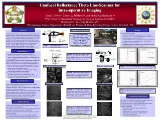
Confocal microscope performs “optical sectioning:”
ILLUMINATION DETECTION/ PATH IMAGING PATH. u. r. DIVIDER STRIP. q max. OBJECTIVE LENS. q min. CONFOCAL SECTION 2h THICKNESS. FOCAL (OBJECT) PLANE. w det. 100 um. 100 um. 100 um. 100 um. 100 um. 100 um. Fold Mirror. Scanning Mirror.

Confocal microscope performs “optical sectioning:”
E N D
Presentation Transcript
ILLUMINATION DETECTION/ PATH IMAGING PATH u r DIVIDER STRIP qmax OBJECTIVE LENS qmin CONFOCAL SECTION 2h THICKNESS FOCAL (OBJECT) PLANE wdet 100 um 100 um 100 um 100 um 100 um 100 um Fold Mirror Scanning Mirror Abstract BEAM SPLITTER A confocal reflectance theta line-scanner is being developed for imaging nuclear, cellular and architectural detail in human tissues in vivo. Preliminary design and experimental results show lateral resolution of 1-5 mm and sectioning (axial resolution) of 2-5 mm is possible within living human skin; thus, nuclear and cellular detail has been imaged in epidermis in vivo. Experimental results are being verified with an analytic model and optical design analysis. An immediate clinical application will be intra-operative imaging of basal cell cancers to guide Mohs micrographic surgery for the precise excision of these cancers. Plane in Focus Small Aperture OPTICAL SYSTEM TISSUE Detector Board Objective Lens Slit Mount Legend: Small Aperture In-focus light Laser Diode Out-of-focus light DETECTOR linear polarizer detection slit width 7.5 mm scanner analyzer diode laser focussing lens f = 125 mm linear detector pixel size 7.5 mm 1024 pixels cylindrical lens f = 200 mm Results Introduction quarter-wave plate • Design and Development; • Axial line spread function measurements show that the sectioning is 1.6 – 9.8 mm for detection slits of width 5-100 um under nominal conditions (Figure 7). • Lateral resolution of 0.8 – 2 mm have been measured with 25, 50, 100 mm and no slit widths (Figure 8). Note: Lateral resolution = 5 mm at the detector. • Preliminary images of epidermis appear comparable to those with point scanning confocal microscopy. • Confocal microscope performs “optical sectioning:” • A thin section within tissue is imaged non-invasively, • mm-level three-dimensional resolution and high contrast is achieved (Figure 1). • Line scanning is simpler and may offer resolution, contrast and depth of imaging performance comparable to point scanning. • Basal cell cancers (BCCs) are among the fastest growing skin cancers (>1.2 million new cases every year in the USA alone); • Precise microsurgical excision is performed by a procedure known an Mohs micrographic surgery. • Mohs surgery is guided by frozen histology of multiple excisions, and is thus inefficient and slow. • The confocal theta line-scanner may enable • Imaging of BCCs directly on patients in real-time, • Guidance of Mohs surgery, thus reducing the number of excisions and avoiding frozen histology. objective lens f = 17.5 mm divider strip (divides objective lens aperture into two halves) object plane State of the Art • Present: Point scanning confocal microscopes are complex, expensive and difficult to manufacture. • In-progress Research: Theta line-scanner may be simple, robust, inexpensive and easy to manufacture. • Present Standard of Care: Surgical removal of skin cancers with unknown margins and potentially more scarring; surgery is guided by frozen histology performed parallel: processing requires 45 mins per excision, 2-20 excisions per patient. • Proposed: Confocal theta line-scanner for real-time, intraoperative imaging and surgical guidance. Optical Design • Confocal theta microscopy was developed by Koester (1980), Stelzer (1995) and Webb (1999). • We designed and built a theta line-scanning confocal microscope (Figure 2) with specifications as shown in Table 1. • Optimized design based on diffraction for best lateral and axial (section) resolution. • The optical design and system set-up are shown in Figure 3. • In vivo and excised skin specimens were imaged (Figure 4 - 6). • Measurements of the axial and lateral resolution were made. Conclusions/Future Work • Resolution (sectioning) of line-scanner compares well to that provided by current point-scanning technology. • Experimental results of axial and lateral line spread function measurements agree well with theoretical values. • Further work needed; • Aberrated LSF at pupil edges and within skin • Contrast and SNR • Illumination scan / detection de-scan mismatch. • Signal drop-out (illum./detect. path mismatch) • CMOS Detector Sensitivity • Correlation of images to histology Confocal Reflectance Theta Line-Scanner for Intra-operative ImagingPeter J. Dwyer*, Charles A. DiMarzio*, and Milind Rajadhyaksha *s*The Center for Subsurface Sensing and Imaging Systems (CenSSIS),Northeastern University, Boston, MAsDermatology Service, Department of Medicine, Memorial Sloan-Kettering Cancer Center, New York, NY Table 1. - Instrument Specifications Line Scanner Specifications Imaging: 5-20 frames/sec (real-time) Lateral Resolution: 1-3 mm Vertical Section Thickness: 2-5 mm Max Depth: 300 mm Objective: 10x, NA = 0.80 Field of view: 1.0 mm Laser illumination: 830 nm (Diode) Figure 1. – Confocal Microscopy, “Optical Sectioning” Figure 2. – Confocal RTLS Microscope Figure 3. – Confocal Theta Line-Scanning. The intersection of the illumination and detection paths creates confocal probe volume (PSF), (a). Figure 3b illustrates the system layout. Figure 3b. – Optical Layout Figure 3a. – Geometrical Optics Concept Figure 7. – (a) Axial LSF measurement; 10 mm Slit. (b) Axial line spread function measurements for various detection slit widths. Figure 4. – Line scanner confocal images in human skin in vivo using a 50 mm slit. The upper layers of the epidermis contain the stratum corneum (a) and the granular cells (b). Figure 4b – Granular Cells Figure 4a – Stratum Corneum Figure 8. – (a) Lateral LSF Measurement; 50 mm slit. (b) Lateral line spread function measurements for various detection slit widths. Figure 5. - Line scanner confocal images in human skin in vivo using a 50 mm slit. The middle layers of the epidermis containing the spinous cells. The dark nuclei are surrounded by the bright, grainy cytoplasm. Figure 6. - Line scanner confocal images in human skin in vivo using a 50 mm slit. The deeper layers of the epidermis contain basal cells. The bright basal cells are clustered around dermal papillae (dark circles). Acknowledgement: This work is supported in parts by NIH/NCI (Award Number 1R43CA93106 and 2R44CA93106) and the NSF Partnerships in Education and Research Program (Award Number EEC-012931).