Method of obtaining optical sectioning by using structured light in a conventional microscope
190 likes | 493 Vues
Method of obtaining optical sectioning by using structured light in a conventional microscope. Neil MAA, Juskaitis R, Wilson T. Optics Letters. 22 (24):1905-1907 ( 1997). Bio-optics & Microscopy (MEDS 6450) 11/16/2010. Presented by: Mathilde Bonnemasison Leia Shuhaibar Steve Pirnie

Method of obtaining optical sectioning by using structured light in a conventional microscope
E N D
Presentation Transcript
Method of obtaining optical sectioning by using structured light in a conventional microscope Neil MAA, Juskaitis R, Wilson T. Optics Letters. 22 (24):1905-1907 (1997) Bio-optics & Microscopy (MEDS 6450) 11/16/2010 Presented by: MathildeBonnemasison • LeiaShuhaibar Steve Pirnie Ronghua (Ronnie) Yang
Objectives • Overview of the technique • Presentation of the paper • Interesting images created with Structure Illumination • Comparison with Laser scanning Miscroscopy
Methods of Optical Sectioning • Confocal laser-scan microscopy • 3D deconvolution • Nipkow disk • Structured Illumination Goal: Improve contrast & resolution
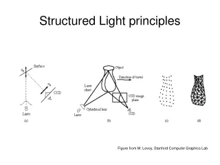
Structured Illumination • Components: • Fluorescence microscope • Cooled CCD camera • Computer plus monitor • Software • Slider – inserted into the plane of the field diaphragm of the illumination beam path • Contains a grid structure with grid lines of defined width
Condensor Tube Lens Objective Field Diaphragm plane Intermediate Image plane Sample plane Image Planes Field diaphragm matched to the focal plane CCD chip
Optical Arrangement Tube Lens Objective Lens Condensor Lens Figure 1. Schematic of the optical arrangement
3 Images 120° apart Reconstructed Image Acquired Images Langhorst MF, Schaffer J, Goetze B.Biotechnology Journal 2009, 4,858-865
Widefield Image: I0=I1+I2+I3 Reconstructed Image: Ip=[(I1-I2)2+(I1-I3)2+(I2-I3)2]1/2
Mirror Experiment µ = ύ is normalized spatial frequency of the grid
Lily Pollen Effective magnification of (50/180)M M= magnification of the objective lens • Grid: 40-line/mm • saw-tooth movement synchronized to the camera frame rate successive camera images corresponded to a spatial shift of 120 degrees in the position of the projected image of the grid • 15 W tungsten halogen lamp as light source • Green filter (bandwidth 100nm) • 30um axial scan with 50X, 0.75 NA objective
Source of Artifacts • Imperfect grid movement perceivable grid lines in the resulting image • Fluctuations in light intensity leads to Δ in intensity (compensate by normalizing using average image intensity) • Bleaching intensity losses that have to be taken into account during calculation • Thicker specimen giving more fluorescence volume use finer grid Other Cons • Sequential image acquisition not well-suited for fast moving sample
Out of Plane Rejection of Light Pinhole aperture blocks out-of focus light • Fewer photons collected than • Widefield fluorescence • only from plane in focus • Also losses from optical path • Worse S/N • But Better Resolution than • Widefield fluorescence • ~30% lateral • Widefield does not have • Axial resolution
Comparing against Confocal Coarser Grid Finer Grid