Download

1 / 31
360 likes | 580 Vues
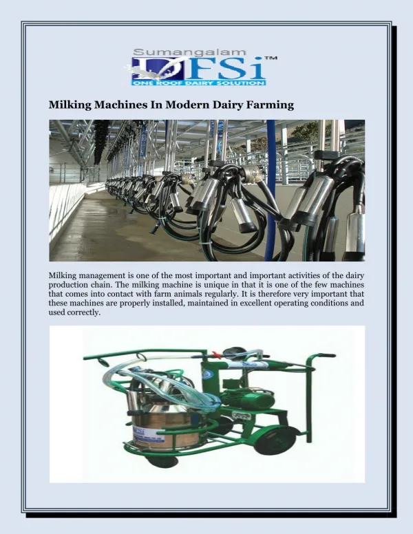
Recommendations for the installation and testing of milking machines. This manual has been prepared by; Mr. Seamas Goggin IMQCS Dr. Edmond Harty IMQCS Mr. George Kearns Secretary, IMQCS Dr. Eddie O’Callaghan Editor , Teagasc Mr. Alan Pearson IMQCS

E N D
Recommendations for the installation and testing of milking machines This manual has been prepared by; Mr. Seamas Goggin IMQCS Dr. Edmond Harty IMQCS Mr. George Kearns Secretary, IMQCS Dr. Eddie O’Callaghan Editor, Teagasc Mr. Alan Pearson IMQCS Mr. Sean Reid IMQCS Mr. Tom Ryan Teagasc The committee wishes to acknowledge the contribution of Margie Egan (Teagasc) in compiling this booklet.
This manual combines Irish Milk Quality Co-operative Society (IMQCS) Guidelines and ISO standards (International Standards Organization) (ISO 5707 (2007), ISO 6690 (2007) and ISO 3918 (2007) into a reference guide for all milking machine installers and advisers in the Republic of Ireland.
USER’S MANUAL The user's manual written in at least one of the country's official languages shall specify a system of measures that ensure that the function, safety and hygiene of the milking machine are maintained during its intended lifetime. This includes instructions for routine servicing and replacement of individual parts. An indication shall be given as to whether particular actions should be performed by the user or if other suitably qualified personnel are needed.
Airflow measuring connections • A1: to enable measurement of effective reserve, manual reserve and regulator leakage: • A2: to enable measurement of leakage into the vacuum and milk systems
VACUUM SYSTEM The ultimate goal is to maintain vacuum at teat end within the intended range. The machine shall be capable of adequate vacuum control and operators shall use the machine with reasonable care and in accordance with the user’s manual. Vacuum deviation: The working vacuum (Vm), after a defined start-up period shall be within ± 2 kPa of the nominal. Regulation sensitivity: Shall not to exceed 1 kPa. Regulation loss shall not exceed 35 l/min of free air or 10 % of the manual reserve, whichever is the greater.
Regulation characteristics and effective reserve • Regulation overshoot shall be less than 2 kPa One of the following requirements shall be fulfilled: • 1. Vacuum drop and undershoot during cluster fall-off test shall be less than 2 kPa.This requirement is more appropriate for large milking systems and where the operators are less careful during attachment • 2. The minimum effective reserve given in Table’s 1-4 is more appropriate for small milking systems (< 8 units) In large milking systems the effective reserve should be sufficient to maintain working vacuum (Vm) within ± 2 kPa during the course of normal milking, including teatcup attachment and removal, liner slip or teatcup/cluster fall, for at least 99 % of the milking time.
Air lines-internal diameter and airflow Airlines shall be large enough so vacuum drop does not seriously affect milking machine function. • Vacuum drop between Vm and Vrshall therefore not exceed 1 kPa. • When Vp > Vm the higher vacuum at Vpincreases power consumption and decreases the vacuum pump capacity. Vpshould preferably not exceed Vm by more than 3 kPa.
Vacuum Pumps The vacuum pump shall have adequate airflow capacity to meet the requirements for milking and cleaning including air used by all ancillary equipment operating during milking and cleaning, whether continuously or intermittently. If more than one vacuum pump is, it shall be possible to isolate pump(s) not in use.
Leakage into the vacuum system Leakage into the vacuum system shall not exceed 5 % of the vacuum pump capacity at the working vacuum and for capacity-controlled vacuum pumps at the pump's maximum capacity.
Pulsation rate, pulsator ratio and pulsation chamber vacuum phases The pulsation rate shall not deviate more than ± 5 % from intended values given in the user's manual. Note: Pulsation rate is typically between 50 cycles/min and 65 cycles/min for cows. The pulsator ratio shall not differ more than ± 5 units of percentage from the values given in the user's manual. The pulsator ratios shall not vary from each other by more than 5 units of percentage. Limping shall not be more than 5 units of percentage except where the milking unit is designed to provide different ratios between the fore- and hindquarters. Phase b shall be not less than 30 % of a pulsation cycle and phase d shall be not less than 150ms. Vacuum drop during phase b shall not be more than 4 kPa below maximum pulsation chamber vacuum. Vacuum during phase d shall not be more than 4 kPa.
Design of milklines • Vacuum drop between the receiver and any point in the milkline shall not exceed 2 kPa with all units operating at the designed milk flow and airflow. • Diameter and slope shown in Table 1 for a mid-level plant are based on milk flow per cow of 5kg/min, 100 l/min transient airflow per slope and 1.5% slope. • Milklines shall have a continuous fall towards the receiver for drainage. • Milklines should be installed to minimize the milk lift and preferably no more than 2 m above the animal standing level.
Air vent and leakage • Total air admission per cluster shall be at least 4 l/min and shall not exceed 12 l/min for cows at the nominal working vacuum. • Leakage into each cluster assembly with the liners and air vent(s) plugged and the vacuum shut-off valve opened shall not exceed 2 l/min.
Vacuum in the milking unit • User's manual shall state, for specified milk flows: The desired average liner vacuum and/or the desired average liner vacuum during phase b and phase d of the pulsation chamber vacuum record. The corresponding nominal vacuum in the milkline based on the average vacuum drop. • For devices not originally fitted to a milking unit between the cluster and the milkline or milking vacuum line, the effect on the milking vacuum conditions shall be stated in the user's manual.
Attachments to the milking unit Devices, including additional necessary connecting tubes, fitted between the cluster or teatcup and the milkline or milking vacuum line, shall not cause any additional vacuum drop greater than 5 kPa at a milk flow of 5 kg/min for cows compared with the same milking unit without those devices.
Regulation loss • With the milking machine operating with liners plugged, connect the airflow meter with a full-bore connection to connection point A1 with the airflow meter closed. Connect a vacuum meter to the connection point Vm. • Record the vacuum as the working vacuum for the milking machine. • Open the airflow meter until the vacuum decreases by 2kPa and record the airflow. • Stop any airflow through regulators that admit air. • Decrease the vacuum by opening the airflow meter to drop the vacuum 2 kPa. • Calculate the regulation loss as the difference between the airflows.
Regulation undershoot, vacuum drop and regulation overshoot for rapid changes in air admission A undershoot 1 phase 1: no teatcup open B vacuum drop 2 phase 2: teatcup(s) are open C overshoot 3 phase 3: teatcup(s) open 4 phase 4: teatcup(s) are closed
Effective reserve for milking • With the milking machine operating connect the airflow meter with a full-bore connection to connection point A1 with the airflow meter closed. Connect a vacuum meter to the connection point Vm. • Record the vacuum as the working vacuum for the milking machine. • Open the airflow meter until the vacuum decreases by 2kPa. • Record the airflow through the airflow meter.
Vacuum regulator leakage • With the milking machine operating connect the airflow meter with a full-bore connection to connection point A1, with no airflow through it. A vacuum meter shall be connected to connection point Vr. • Record the vacuum as the regulator working vacuum. • Decrease the vacuum by 2 kPa by opening the airflow meter and record the airflow. • Stop the airflow through regulator(s). • Open the airflow meter and decrease the vacuum by 2 kPa and record the airflow. • Calculate the regulator leakage as the difference between the airflows.
Vacuum drop in air line • With the milking machine operating connect the airflow meter with a full-bore connection to point A1 with no airflow through it. A vacuum meter shall be connected to point Vm. Record the vacuum as the working vacuum for the milking machine. • Open the airflow meter until the vacuum at Vm decreases by 2kPa and record the working vacuum. • Move the vacuum meter to regulator connection point Vr and record the working vacuum. • Calculate the vacuum drop between Vm and Vr . • Move the vacuum meter to vacuum pump connection point Vp and record the working vacuum. • Calculate the vacuum drop between Vm and Vp.
Leakage in vacuum system • With the milking machine operating with all units plugged connect the airflow meter with a full-bore connection to point A2 with no airflow through it. Connect a vacuum meter to point Vr or Vp. • Record the vacuum as the regulator or vacuum pump working vacuum. • Isolate the vacuum system from the milk system. Stop the airflow through the vacuum regulator. • Adjust the airflow meter until the vacuum is similar to that recorded in Record the working vacuum at the vacuum pump connection point Vp. • Isolate the vacuum pump from the rest of the vacuum system. Connect the airflow meter directly to vacuum pump with a full-bore connection. • Calculate the vacuum system leakage as the difference between the airflow recorded with the vacuum system disconnected and the airflow with the vacuum system connected.
Milk system leakage • With the milking machine operating connect the airflow meter with a full-bore connection to connection point A2 with no airflow through it. Connect vacuum meter to connection point Vr or Vp. • Record the vacuum as the regulator or vacuum pump working vacuum. • Stop the airflow through the vacuum regulator. Stop or isolate the pulsators and all vacuum operated equipment. Plug all air admissions. • Adjust the airflow . • Isolate the milk system. • Record the airflow. • Calculate the milk system leakage as the difference between the airflows.
Teatcup or cluster fall-off air inlet. • With the milking machine operating without the vacuum regulator, and airflow meter connected to point A1 with a full-bore connection and a vacuum meter connected to point Vm, adjust the airflow meter until the vacuum is 50 kPa. • Open one teatcup or one cluster with the shut-off valve open and adjust the airflow meter until the vacuum is the same as above.
Example of prediction of a vacuum pump capacity • Data: • a) A herringbone milking parlour with 12 milking units direct to line, automatic cluster removers and automatic shut-off valves at claw situated <300m above sea level • b) One milker • c) Working vacuum: 50 kPa • d) Milkline diameter: 73 mm • e) Airflow use for each pulsator: 35 l/min • f) Airflow inlet in the clusters: 12 l/min • g) Airflow for ancillary equipment per cluster: 12 l/min • h) Wash slug speed 8 m/s • i) Peak milk flow 5 kg/min • j) Milkline slope 1.5%
Calculations: The effective reserve capacity for milking will be: 500 + {(12 – 10) x 10} = 520 l/min. The airflow use for cleaning at 50 kPa should be 1004 l/mm for a milkline with a diameter of 73 mm. (Table A4). Airflow use for the milking units (claw air inlets + pulsators) will be 12 x(12 + 35) l/min = 564 l/min. The milking units will consume about the same amount of airflow during milking and cleaning. Total airflow use during milking will be 520 l/min + 564 l/min =1084 l/min. Total airflow use during cleaning will be 1004 l/min + 564 l/min =1568 l/min In this example the capacity for cleaning is the larger and therefore the base of the pump dimensioning. Leakage into the milk system: 10 l/min + (2 x 12) l/min =34 l/min Losses due to ancillary equipment 12x12= 144 l/min Total :1568 l/min + 34 l/min + 144 l/min = 1746 l/min Regulation loss is 10% of the manual reserve. The effective reserve was 520 l/min and is smaller than the manual reserve. Consequently: Manual reserve = 520 l/min x 100/(100 – 10) = 578 l/min Regulation loss = 578 l/min x 10/100 = 58 l/min Total: 1746 l/min + 58 l/min = 1804 l/min Leakages into the air lines are equal to 5% of the pump capacity that is Vacuum system leakage: 1804 l/min x 5/(100 – 5) = 95 l/min; Total: 1804 l/min + 95 l/min = 1899 l/min The minimum nominal capacity of the vacuum pump must therefore be 1899 l/min
Calibration • A calibration service for airflow meters, electronic pulsation analysers and vacuum meters is available at Teagasc, Moorepark Dairy Production Research Centre, Fermoy, Co Cork. • A portable milk flow simulator is also available at Teagasc, Moorepark for establishing vacuum losses in milking systems installed on farms. The flow simulation data provides design guidelines for optimum design of milking systems.