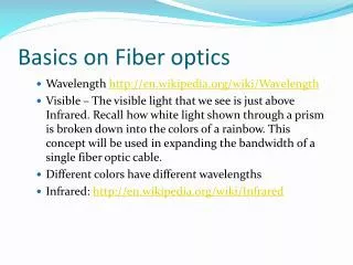
Download
1 / 50
580 likes | 1.03k Vues
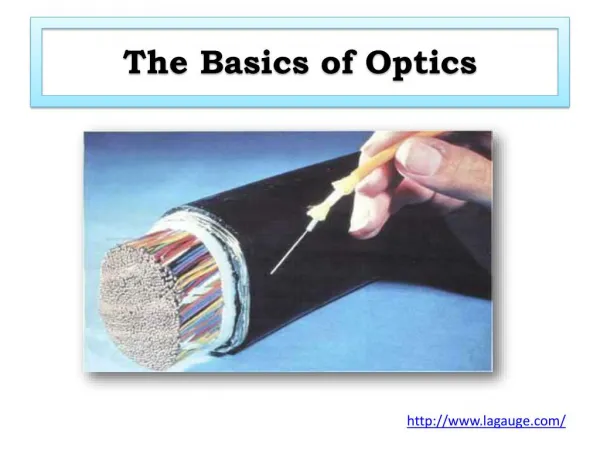
The Basics of Fiber Optics. Ch 2 Fiber Optics Technician’s Manual, 3 rd . Ed Jim Hayes. Optical Fiber. Fiber v. Copper. Optical fiber transmits light pulses Can be used for analog or digital transmission Voice, computer data, video, etc.

E N D
The Basics of Fiber Optics Ch 2 Fiber Optics Technician’s Manual, 3rd. Ed Jim Hayes
Fiber v. Copper • Optical fiber transmits light pulses • Can be used for analog or digital transmission • Voice, computer data, video, etc. • Copper wires (or other metals) can carry the same types of signals with electrical pulses
Advantages of Fiber • Fiber has these advantages compared with metal wires • Bandwidth – more data per second • Longer distance • Faster • Special applications like medical imaging and quantum key distribution are only possible with fiber because they use light directly
Elements of a Fiber Data Link • Transmitter emits light pulses (LED or Laser) • Connectors and Cables passively carry the pulses • Receiver detects the light pulses Cable Transmitter Receiver
Fiber Fiber Fiber Fiber Repeater Repeater Repeater Repeaters • For long links, repeaters are needed to compensate for signal loss
Optical Fiber • Core • Glass or plastic with a higher index of refraction than the cladding • Carries the signal • Cladding • Glass or plastic with a lower index of refraction than the core • Buffer • Protects the fiber from damage and moisture • Jacket • Holds one or more fibers in a cable
Index of refraction Singlemode Fiber • Singlemode fiber has a core diameter of 8 to 9 microns, which only allows one light path or mode • Images from arcelect.com (Link Ch 2a)
Multimode Step-Index Fiber • Multimode fiber has a core diameter of 50 or 62.5 microns (sometimes even larger) • Allows several light paths or modes • This causes modal dispersion – some modes take longer to pass through the fiber than others because they travel a longer distance • See animation at link Ch 2f Index of refraction
Index of refraction Multimode Graded-Index Fiber • The index of refraction gradually changes across the core • Modes that travel further also move faster • This reduces modal dispersion so the bandwidth is greatly increased
Step-index and Graded-index • Step index multimode was developed first, but rare today because it has a low bandwidth (50 MHz-km) • It has been replaced by graded-index multimode with a bandwidth up to 2 GHz-km
Plastic Optical Fiber • Large core (1 mm) step-index multimode fiber • Easy to cut and work with, but high attenuation (1 dB / meter) makes it useless for long distances
Sources and Wavelengths • Multimode fiber is used with • LED sources at wavelengths of 850 and 1300 nm for slower local area networks • Lasers at 850 and 1310 nm for networks running at gigabits per second or more
Sources and Wavelengths • Singlemode fiber is used with • Laser sources at 1300 and 1550 nm • Bandwidth is extremely high, around 100 THz-km
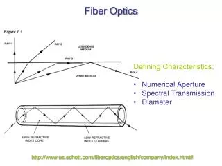
Fiber Optic Specifications • Attenuation • Loss of signal, measured in dB • Dispersion • Blurring of a signal, affects bandwidth • Bandwidth • The number of bits per second that can be sent through a data link • Numerical Aperture • Measures the largest angle of light that can be accepted into the core
Attenuation and Dispersion • See animation at link Ch 2e
Measuring Bandwidth • The bandwidth-distance product in units of MHz×km shows how fast data can be sent through a cable • A common multimode fiber with bandwidth-distance product of 500 MHz×km could carry • A 500 MHz signal for 1 km, or • A 1000 MHz signal for 0.5 km • From Wikipedia
Numerical Aperture • If the core and cladding have almost the same index of refraction, the numerical aperture will be small • This means that light must be shooting right down the center of the fiber to stay in the core • See Link Ch 4d
Fiber Types and Specifications • From Lennie Lightwave (www.jimhayes.com/lennielw/fiber.html)
Popular Fiber Types • At first there were only two common types of fiber • 62.5 micron multimode, intended for LEDs and 100 Mbps networks • There is a large installed base of 62.5 micron fiber • 8 micron single-mode for long distances or high bandwidths, requiring laser sources • Corning’s SMF-28 fiber is the largest base of installed fiber in the world (links Ch 2j, 2k)
Gigabit Ethernet • 62.5 micron multimode fiber did not have enough bandwidth for Gigabit Ethernet (1000 Mbps) • LEDs cannot be used as sources for Gigabit Ethernet – they are too slow • So Gigabit Ethernet used a new, inexpensive source: • Vertical Cavity Surface Emitting Laser (VCSEL)
Multimode Fiber Designed for VCSELs • First came laser-rated 50 micron multimode • Bandwidth 500 MHz-km at 850 nm • Then came laser-optimized 50 micron multimode • Bandwidth 2000 MHz-km at 850 nm • Distinctive aqua-colored jacket • See links Ch 2g, 2h, 2i
Don’t Mix Fiber Types • You can’t mix singlemode and multimode fiber – you lose 20 dB at the junction (99% of the light!) • Mixing 50 micron and 62.5 micron multimode is not as bad, but you lose 3 dB (half the power) which is usually unacceptable
Flash Cards • To memorize this stuff, I use online flash cards • Go to samsclass.info • Click on CNIT 211 • Click on Flashcards • Choose Ch 2a: Fiber Types
Three Methods • Modified Chemical Vapor Deposition (MCVD) • Outside Vapor Deposition (OVD) • Vapor Axial Deposition (VAD)
Modified Chemical Vapor Deposition (MCVD) • A hollow, rotating glass tube is heated with a torch • Chemicals inside the tube precipitate to form soot • Rod is collapsed to crate a preform • Preform is stretched in a drawing tower to form a single fiber up to 10 km long • Image from thefoa.org
Outside Vapor Deposition (OVD) • A mandrel is coated with a porous preform in a furnace • Then the mandrel is removed and the preform is collapsed in a process called sintering • Image from csrg.ch.pw.edu.pl
Vapor Axial Deposition (VAD) • Preform is fabricated continuously • When the preform is long enough, it goes directly to the drawing tower • Image from csrg.ch.pw.edu.pl
Drawing • The fiber is drawn from the preform and then coated with a protective coating
Index of Refraction • When light enters a dense medium like glass or water, it slows down • The index of refraction (n) is the ratio of the speed of light in vacuum to the speed of light in the medium • Water has n = 1.3 • Light takes 30% longer to travel through it • Fiber optic glass has n = 1.5 • Light takes 50% longer to travel through it
Step-index Multimode • Large core size, so source power can be efficiently coupled to the fiber • High attenuation (4-6 dB / km) • Low bandwidth (50 MHz-km) • Used in short, low-speed datalinks • Also useful in high-radiation environments, because it can be made with pure silica core
Graded-index Multimode • Useful for “premises networks” like LANs, security systems, etc. • 62.5/125 micron has been most widely used • Works well with LEDs, but cannot be used for Gigabit Ethernet • 50/125 micron fiber and VSELS are used for faster networks
Singlemode FIber • Best for high speeds and long distances • Used by telephone companies and CATV
Attenuation • Modern fiber material is very pure, but there is still some attenuation • The wavelengths used are chosen to avoid absorption bands • 850 nm, 1300 nm, and 1550 nm • Plastic fiber uses 660 nm LEDs • Image from iec.org (Link Ch 2n)
Three Types of Dispersion • Dispersion is the spreading out of a light pulse as it travels through the fiber • Three types: • Modal Dispersion • Chromatic Dispersion • Polarization Mode Dispersion (PMD)
Modal Dispersion • Modal Dispersion • Spreading of a pulse because different modes (paths) through the fiber take different times • Only happens in multimode fiber • Reduced, but not eliminated, with graded-index fiber
Chromatic Dispersion • Different wavelengths travel at different speeds through the fiber • This spreads a pulse in an effect named chromatic dispersion • Chromatic dispersion occurs in both singlemode and multimode fiber • Larger effect with LEDs than with lasers • A far smaller effect than modal dispersion
Polarization Mode Dispersion • Light with different polarization can travel at different speeds, if the fiber is not perfectly symmetric at the atomic level • This could come from imperfect circular geometry or stress on the cable, and there is no easy way to correct it • It can affect both singlemode and multimode fiber.
Modal Distribution • In graded-index fiber, the off-axis modes go a longer distance than the axial mode, but they travel faster, compensating for dispersion • But because the off-axis modes travel further, they suffer more attenuation
Equilibrium Modal Distribution • A long fiber that has lost the high-order modes is said to have an equilibrium modal distribution • For testing fibers, devices can be used to condition the modal distribution so measurements will be accurate
Mode Stripper • An index-matching substance is put on the outside of the fiber to remove light travelling through the cladding • Figure from fiber-optics.info (Link Ch 2o)
Mode Scrambler • Mode scramblers mix light to excite every possible mode of transmission within the fiber • Used for accurate measurements of attenuation • Figure from fiber-optics.info (Link Ch 2o)
Mode Filter • Wrapping the fiber around a 12.5 mm mandrel • Exceeds the critical angle for total internal reflection for very oblique modes • The high-order modes leak into the cladding and are lost • That creates an equilibrium modal distribution • Allows an accurate test with a short test cable • Figure from fiber-optics.info (Link Ch 2o)
Power Out Power In Data Link Optical Loss in dB (decibels) • If the data link is perfect, and loses no power • The loss is 0 dB • If the data link loses 50% of the power • The loss is 3 dB, or a change of – 3 dB • If the data link loses 90% of the power • The loss is 10 dB, or a change of – 10 dB • If the data link loses 99% of the power • The loss is 20 dB, or a change of – 20 dB dB = 10 log (Power Out / Power In)
Absolute Power in dBm • The power of a light is measured in milliwatts • For convenience, we use the dBm units, where -20 dBm = 0.01 milliwatt -10 dBm = 0.1 milliwatt 0 dBm = 1 milliwatt 10 dBm = 10 milliwatts 20 dBm = 100 milliwatts