Download
1 / 63
720 likes | 1.31k Vues
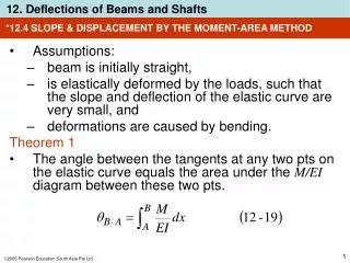
*12.4 SLOPE & DISPLACEMENT BY THE MOMENT-AREA METHOD. Assumptions: beam is initially straight, is elastically deformed by the loads, such that the slope and deflection of the elastic curve are very small, and deformations are caused by bending. Theorem 1

E N D
*12.4 SLOPE & DISPLACEMENT BY THE MOMENT-AREA METHOD • Assumptions: • beam is initially straight, • is elastically deformed by the loads, such that the slope and deflection of the elastic curve are very small, and • deformations are caused by bending. Theorem 1 • The angle between the tangents at any two pts on the elastic curve equals the area under the M/EI diagram between these two pts.
*12.4 SLOPE & DISPLACEMENT BY THE MOMENT-AREA METHOD Theorem 1
*12.4 SLOPE & DISPLACEMENT BY THE MOMENT-AREA METHOD Theorem 2 • The vertical deviation of the tangent at a pt (A) on the elastic curve w.r.t. the tangent extended from another pt (B) equals the moment of the area under the ME/I diagram between these two pts (A and B). • This moment is computed about pt (A) where the vertical deviation (tA/B) is to be determined.
*12.4 SLOPE & DISPLACEMENT BY THE MOMENT-AREA METHOD Theorem 2
*12.4 SLOPE & DISPLACEMENT BY THE MOMENT-AREA METHOD Procedure for analysis M/EI Diagram • Determine the support reactions and draw the beam’s M/EI diagram. • If the beam is loaded with concentrated forces, the M/EI diagram will consist of a series of straight line segments, and the areas and their moments required for the moment-area theorems will be relatively easy to compute. • If the loading consists of a series of distributed loads, the M/EI diagram will consist of parabolic or perhaps higher-order curves, and we use the table on the inside front cover to locate the area and centroid under each curve.
*12.4 SLOPE & DISPLACEMENT BY THE MOMENT-AREA METHOD Procedure for analysis Elastic curve • Draw an exaggerated view of the beam’s elastic curve. • Recall that pts of zero slope and zero displacement always occur at a fixed support, and zero displacement occurs at all pin and roller supports. • If it is difficult to draw the general shape of the elastic curve, use the moment (M/EI) diagram. • Realize that when the beam is subjected to a +ve moment, the beam bends concave up, whereas -ve moment bends the beam concave down.
*12.4 SLOPE & DISPLACEMENT BY THE MOMENT-AREA METHOD Procedure for analysis Elastic curve • An inflection pt or change in curvature occurs when the moment if the beam (or M/EI) is zero. • The unknown displacement and slope to be determined should be indicated on the curve. • Since moment-area theorems apply only between two tangents, attention should be given as to which tangents should be constructed so that the angles or deviations between them will lead to the solution of the problem. • The tangents at the supports should be considered, since the beam usually has zero displacement and/or zero slope at the supports.
*12.4 SLOPE & DISPLACEMENT BY THE MOMENT-AREA METHOD Procedure for analysis Moment-area theorems • Apply Theorem 1 to determine the angle between any two tangents on the elastic curve and Theorem 2 to determine the tangential deviation. • The algebraic sign of the answer can be checked from the angle or deviation indicated on the elastic curve. • A positive B/A represents a counterclockwise rotation of the tangent at B w.r.t. tangent at A, and a +ve tB/A indicates that pt B on the elastic curve lies above the extended tangent from pt A.
EXAMPLE 12.7 Determine the slope of the beam shown at pts B and C. EI is constant.
EXAMPLE 12.7 (SOLN) M/EI diagram: See below. Elastic curve: The force P causes the beam to deflect as shown.
EXAMPLE 12.7 (SOLN) Elastic curve: The tangents at B and C are indicated since we are required to find B and C. Also, the tangent at the support (A) is shown. This tangent has a known zero slope. By construction, the angle between tan A and tan B, B/A, is equivalent to B, or
EXAMPLE 12.7 (SOLN) Moment-area theorem: Applying Theorem 1, B/A is equal to the area under the M/EI diagram between pts A and B, that is,
EXAMPLE 12.7 (SOLN) Moment-area theorem: The negative sign indicates that angle measured from tangent at A to tangent at B is clockwise. This checks, since beam slopes downward at B. Similarly, area under the M/EI diagram between pts A and C equals C/A. We have
EXAMPLE 12.8 Determine the displacement of pts B and C of beam shown. EI is constant.
EXAMPLE 12.8 (SOLN) M/EI diagram: See below. Elastic curve: The couple moment at C cause the beam to deflect as shown.
EXAMPLE 12.8 (SOLN) Elastic curve: The required displacements can be related directly to deviations between the tangents at B and A and C and A. Specifically, B is equal to deviation of tan A from tan B,
EXAMPLE 12.8 (SOLN) Moment-area theorem: Applying Theorem 2, tB/A is equal to the moment of the shaded area under the M/EI diagram between A and B computed about pt B, since this is the pt where tangential deviation is to be determined. Hence,
EXAMPLE 12.8 (SOLN) Moment-area theorem: Likewise, for tC/A we must determine the moment of the area under the entire M/EI diagram from A to C about pt C. We have Since both answers are –ve, they indicate that pts B and C lie below the tangent at A. This checks with the figure.
12.5 METHOD OF SUPERPOSITION • The differential eqn EI d4/dx4 = w(x) satisfies the two necessary requirements for applying the principle of superposition • The load w(x) is linearly related to the deflection (x) • The load is assumed not to change significantly the original geometry of the beam or shaft.
EXAMPLE 12.16 Steel bar shown is supported by two springs at its ends A and B. Each spring has a stiffness k = 45 kN/m and is originally unstretched. If the bar is loaded with a force of 3 kN at pt C, determine the vertical displacement of the force. Neglect the weight of the bar and take Est = 200 GPa, I = 4.687510-6 m.
EXAMPLE 12.16 (SOLN) End reactions at A and B are computed and shown. Each spring deflects by an amount
EXAMPLE 12.16 (SOLN) If bar is considered rigid, these displacements cause it to move into positions shown. For this case, the vertical displacement at C is
EXAMPLE 12.16 (SOLN) We can find the displacement at C caused by the deformation of the bar, by using the table in Appendix C. We have
EXAMPLE 12.16 (SOLN) Adding the two displacement components, we get
12.6 STATICALLY INDETERMINATE BEAMS AND SHAFTS • A member of any type is classified as statically indeterminate if the no. of unknown reactions exceeds the available no. of equilibrium eqns. • Additional support reactions on beam that are not needed to keep it in stable equilibrium are called redundants. • No. of these redundants is referred to as the degree of indeterminacy.
12.7 STATICALLY INDETERMINATE BEAMS AND SHAFTS: METHOD OF INTEGRATION • For a statically indeterminate beam, the internal moment M can be expressed in terms of the unknown redundants. • After integrating this eqn twice, there will be two constants of integration and the redundants to be found. • The unknowns can be found from the boundary and/or continuity conditions for the problem.
EXAMPLE 12.17 Beam is subjected to the distributed loading shown. Determine the reactions at A. EI is a constant.
EXAMPLE 12.17 (SOLN) Elastic curve: Beam deflects as shown. Only one coordinate x is needed. For convenience, we will take it directed to the right, since internal moment is easy to formulate.
EXAMPLE 12.17 (SOLN) Moment function: Beam is indeterminate to first degree as indicated from the free-body diagram. We can express the internal moment M in terms of the redundant force at A using segment shown below.
EXAMPLE 12.17 (SOLN) Moment function: Slope and elastic curve: Applying Eqn 12-10,
EXAMPLE 12.17 (SOLN) Slope and elastic curve: The three unknowns Ay, C1 and C2 are determined from the boundary conditions x = 0, = 0; x = L, d/dx = 0; and x = L, = 0. Applying these conditions yields
EXAMPLE 12.17 (SOLN) Slope and elastic curve: Solving, Using the result for Ay, the reactions at B can be determined from the equations of equilibrium. Show that Bx = 0. By = 2w0L/5 and MB= w0L2/15
12.8 STATICALLY INDETERMINATE BEAMS AND SHAFTS: MOMENT-AREA METHOD • Draw the ME/I diagrams such that the redundants are represented as unknowns. • Apply the 2 moment-area theorems to get the relationships between the tangents on elastic curve to meet conditions of displacement and/or slope at supports of beam. • For all cases, no. of compatibility conditions is equivalent to no. of redundants.
12.8 STATICALLY INDETERMINATE BEAMS AND SHAFTS: MOMENT-AREA METHOD Moment diagrams constructed by method of superposition • Since moment-area theorems needs calculation of both the area under the ME/I diagram and centroidal location of this area, the method of superposition can be used to combine separate ME/I diagrams for each of the known loads. • This will be relevant if the resultant moment diagram is of a complicated shape.
12.8 STATICALLY INDETERMINATE BEAMS AND SHAFTS: MOMENT-AREA METHOD Moment diagrams constructed by method of superposition • Most loadings on beams are a combination of the four loadings as shown.
12.8 STATICALLY INDETERMINATE BEAMS AND SHAFTS: MOMENT-AREA METHOD
12.8 STATICALLY INDETERMINATE BEAMS AND SHAFTS: MOMENT-AREA METHOD
EXAMPLE 12.20 Beam is subjected to couple moment at its end C as shown. Determine the reaction at B. EI is constant.
EXAMPLE 12.20 (SOLN) M/EI Diagram: Free-body diagram as shown. By inspection, beam is indeterminate to first degree. To get a direct solution, choose By as the redundant. Using superposition, the M/EI diagrams forBy and M0, each applied to the simply supported beam are shown.
EXAMPLE 12.20 (SOLN) Elastic curve: Elastic curve as shown. Tangents at A, B and C has been established. Since A = B = C = 0, then tangential deviations shown must be proportional,
EXAMPLE 12.20 (SOLN) Elastic curve: From ME/I diagram, we have
EXAMPLE 12.20 (SOLN) Elastic curve: Substituting into Eqn (1), we have Equations of equilibrium: Reactions at A and C can now be determined from the eqns of equilibrium. Show that Ax = 0, Cy = 5M0/4L, and Ay = M0/4L.
EXAMPLE 12.20 (SOLN) Equations of equilibrium: From figure shown, this problem can also be worked out in terms of the tangential deviations,
12.9 STATICALLY INDETERMINATE BEAMS AND SHAFTS: METHOD OF SUPERPOSITION • First, identify the redundant support reactions on the beam. • Remove these reactions from the beam to get a primary beam that is statically determinate and stable and subjected to external load only. • Add to this beam with a series of similarly supported beams, each with a separate redundant, then by principle of superposition, the final loaded beam is obtained. • After computing the redundants, the other reactions on the beam determined from the eqns of equilibrium. • This method of analysis is sometimes called the force method.
12.9 STATICALLY INDETERMINATE BEAMS AND SHAFTS: METHOD OF SUPERPOSITION Procedure for analysis Elastic curve • Specify unknown redundant forces or moments that must be removed from the beam in order to make it statically determinate and stable. • Use principle of superposition, draw the statically indeterminate beam and show it to be equal to a sequence of corresponding statically determinate beams. • The first beam (primary) supports the same external loads as the statically indeterminate beam, and each of the other beams “added” to the primary beam shows the beam loaded with a separate single redundant force or moment.
12.9 STATICALLY INDETERMINATE BEAMS AND SHAFTS:METHOD OF SUPERPOSITION Procedure for analysis Elastic curve • Sketch the deflection curve for each beam and indicate symbolically the displacement or slope at the pt of each redundant force or moment. Compatibility equations • Write a compatibility eqn for the displacement or slope at each pt where there is a redundant force or moment. • Determine all the displacements or slopes using an appropriate method explained in chapter 12.212.5. • Substitute the results into the compatibility eqns and solve for the unknown redundants.
12.9 STATICALLY INDETERMINATE BEAMS AND SHAFTS: METHOD OF SUPERPOSITION Procedure for analysis Compatibility equations • If a numerical value for a redundant is +ve, it has the same sense of direction as originally assumed. • Similarly, a –ve numerical value indicates the redundant acts opposite to its assumed sense of direction. Equilibrium equations • Once the redundant forces and/or moments have been determined, the remaining unknown reactions can be found from the eqns of equilibrium applied to the loadings shown on the beam’s free-body diagram.
EXAMPLE 12.22 Determine the reactions on the beam shown. Due to loading and poor construction, the roller support at B settles 12 mm. Take E = 200 GPa and I = 80(106) mm4.
EXAMPLE 12.22 (SOLN) Principle of superposition By inspection, beam is indeterminate to the first degree. Roller support at B is chosen as the redundant. Principle of superposition is shown. Here, By is assumed to act upwards on the beam.
EXAMPLE 12.22 (SOLN) Compatibility equation With reference to pt B, we require Using table in Appendix C, displacements are