AVR ATmega128 microcontroller
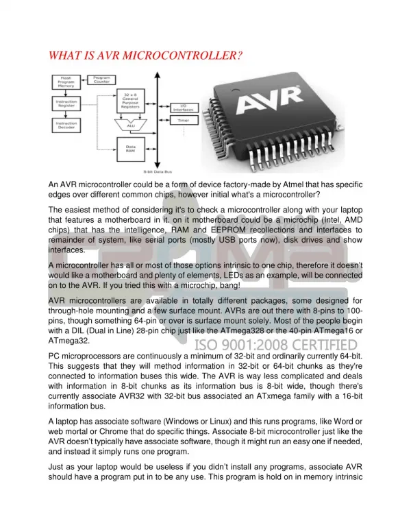
AVR ATmega128 microcontroller. Topics. ATmega128 hardware Assembly Specialties I/O port s Interrupts Timing Development tools. ATmega128 hardware. CPU: 8 bit, 16 MHz 133 RISC instructions Typically 1 clk/instruction (except branch) Mem ory : 128K Flash (program)

AVR ATmega128 microcontroller
E N D
Presentation Transcript
Topics • ATmega128 hardware • Assembly • Specialties • I/O ports • Interrupts • Timing • Development tools
ATmega128 hardware • CPU: • 8 bit, 16 MHz • 133 RISC instructions • Typically 1 clk/instruction(except branch) • Memory: • 128K Flash (program) • 4K EEPROM + 4K internal SRAM (data) • 32 register (16 upper special, 3 register pairs) Harvard-architecture
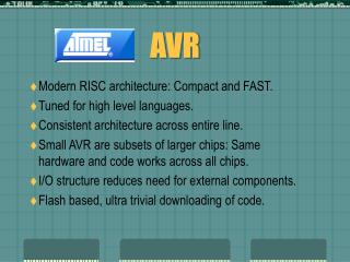
ATmega128 programming • AVR: Atmel RISC processor family,ATmega128: AVR processor 128K flash memory („Advanced Virtual RISC”) • Development tool: AVRStudio • Assembly és C language (AVR-GCC, WinAVR) • Programming (ISP, In System Programming) and debug (JTAG-ICE, In Circuit Emulation) • Simulation environment (mikrocontroller + integrated peripherals)
AVRStudio IDE (IDE: Integrated Development Environment)
Topics • ATmega128 hardware • Assembly • Specialties • I/O ports • Interrupts • Timing • Development tools
Compiling C code Preprocessor C source (makros (#define; #include…) gcc –E prog.c Compiler Assembly code (architecture dependant, optimized) gcc –S prog.c Assembler Object code Libraries Linker Executable (.com, .exe, ELF…)
Assembly introduction • Low-level programming language • Architecture dependant (pl. x86, PPC, AVR…) • Between C and machine code – compact, • Application: mainly small embedded systems (pl. PIC, AVR) • For large projects: asm is expensive, inflexible, hard to manage; C compilers are well-optimized • Low-level routines • Computations intensive tasks (mathematics, graphics) • reverse engineering
AVR assembly - registers • RISC instruction set, load/store architecture: Registers: • 32, 8 bit wide (r0…r31) • All operations are done through registers • Last six serves as register pairs • Implement 3 16 bit registers (X, Y, Z)
AVR assembly – special registers • Stastus register (SREG) - flags • Carry, Zero, Global Interrupt Enable/Disable… • Some instructions set the flags (e.g. arithmetic), other allow branching based on flag value • mapped to I/O address space, therefore should be save in the IT routine: PUSH temp PUSH SREG helyett IN temp, SREG PUSH temp
AVR assembly – special registers • Stack pointer • To store return address of subroutines, or save/restore variables (push, pop) • Grows from higher to lower addrress • 2 byte register • Stack stored in the data SRAM • FILO • Program Counter • Address of the actual instruction • During CALL or IT it is save to the heap; RET/RETI loads from heap at the end of a subroutine/IT routine ldi temp, LOW(RAMEND) out SPL, temp ldi temp, HIGH(RAMEND) out SPH, temp
AVR assembly - instructions mnemonic ldi temp, 0xA5 ; 10100101 out PORTC, temp ; port write arguments (operands) comment !!!!!
AVR assembly - instructions instruction arguments ldi temp, 0xA5 ; 10100101 out PORTC, temp ; port write SREG
AVR assembly – instr. types • Arithmetic and logic • Branch, jump • Data movement • Bit manipulation, bit test
AVR assembly – instructions Arithmetic and logic Move Bit op., others
AVR assembly - jumps • JMP: unconditional jump E.g. forever loop: • CALL, RET: subroutine call, return (HEAP) • RETI: return from IT Subroutine: Construct in C:
AVR assembly – conditional jump • Equality test CPSE (compare, skip if equal) skips the next instruction (L2) if the two opernads are equal, otherwise executed normally (L1). Easy to mess up - DRAW A FLOWCHART!
AVR assembly – branch • switch / case Note: BREQ can only jump 64 bytes!
AVR assembly – „for” • Long „for” cycle (more than 1 byte): Using 2 byte instructions is also possible (SBIW vagy ADIW).
AVR assembly – directives .include "m128def.inc" • ATmega128 registers and bit specification file .def temp = r16 • register r16 renamed to temp .equ tconst = 100 • Defining a constant value .org $0046 • defining the memory adress of the next instruction M_LOOP: • Label (e.g. for jumps)
Topics • ATmega128 hardware • Assembly • Specialties • I/O ports • Interrupts • Timing • Development tools
I/O ports • 3 I/O registers per port, bitwise configuration • DDRx: direction (1: out, 0: in) • PORTx: • DDR=out: output data • DDR=in: pullup resistor or floating • PINx: actual value of the PIN! • DDR=out: DDRx (with 1 clk latency) • DDR=in: input data • IN, OUT instructions for I/O addresses, LDS, STSfor memory mapped (PORTG)
I/O ports direction DDRx DDRx value Output value / pullup PORTx PORTx value PINx (out/) input value
L H I/O ports • Writing output data (e.g. LEDs): ldi temp, 0xff ; 8 bit output out DDRC, temp out PORTC, temp ; turn on all LEDs • Reading data (PORTG, e.g. switch): ldi temp, 0xFF sts PORTG, temp ; non tri-state ldi temp, 0x00 ; input sts DDRG, temp ; lds temp, PING ; read PIN
Interrupts • Single-level IT • Incoming IT clears the IT enable bit, RETI re-enables it – DO NOT do these in your IT routine! • IT vector table • Enable the different interrupt sources • Enable global interrupt: SEI • In the IT routine: • Save the status register • Save all used registers • Do the IT routine • Restore the saved registers • Restore status register
jmp TIMER_IT; Timer0 Compare Match Handler IT vector table .org $0000 ; Define start of Code segment jmp RESET ; Reset Handler, jmp is 2 word instruction reti ; INT0 Handler on $0002, dummy nop reti ; INT1 Handler, if INTn used, 'reti' and 'nop' ; will be replaced by 'jmp INTn_Handler_Address' nop reti ; INT2 Handler nop ... reti ; Timer1 Compare Match B Handler nop reti ; Timer1 Overflow Handler nop reti nop reti ; Timer0 Overflow Handler nop .org $0046 ; MAIN program...
IT routine TIMER_IT: ; save status register and temp register into heap push temp in temp, SREG push temp <...IT-handling...> ; restore temp and then status pop temp out SREG, temp pop temp reti ; return
Timing • Without IT: • „For loop” – delay loop • Polling timer counter (peripheral) • Easy to debug, realize • Imprecise, occupies all CPU time • Using timer IT • Prescaler for less-frequent IT • Enable timer IT • SW counter is required for large delays
Timing with IT ; ***** Timer 0 init ***** ; prescaler ldi temp,0b00001111 ; 0....... ; FOC=0 ; .0..1... ; WGM=10 (clear timer on compare match) ; ..00.... ; COM=00 (output disable) ; .....111 ; CS0=111 (CLK/1024) out TCCR0,temp ; Timer 0 TCCR0 register ; compare register ldi temp,108 ; 11059200Hz/1024 = 108*100 out OCR0,temp ; Timer 0 OCR0 register ; Timer 0 IT enabled, others disabled ldi temp,0b00000010 ; 000000.. ; Timer2,1 IT disabled ; ......1. ; OCIE0=1 - match ; .......0 ; TOIE0=0 - overflow out TIMSK,temp ; Timer IT Mask register sei ; global IT enabled