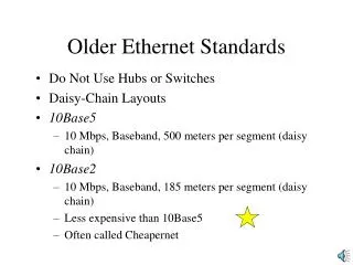
Thinnet (10Base2)
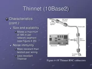
Thinnet (10Base2). Characteristics (cont.): Size and scalability Allows a maximum of 185 m per network segment (see Figure 4-20) Noise immunity More resistant than twisted-pair wiring Less resistant Thicknet. Figure 4-19: Thinnet BNC connectors. Thinnet (10Base2). Signal bounce

Thinnet (10Base2)
E N D
Presentation Transcript
Thinnet (10Base2) • Characteristics (cont.): • Size and scalability • Allows a maximum of 185 m per network segment (see Figure 4-20) • Noise immunity • More resistant than twisted-pair wiring • Less resistant Thicknet Figure 4-19: Thinnet BNC connectors
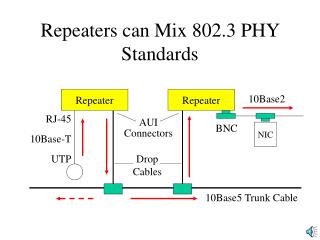
Thinnet (10Base2) • Signal bounce • Caused by improper termination on a bus network • Travels endlessly between two ends of network • Prevents new signals from getting through Figure 4-20: A 10Base2 Ethernet network
Twisted-Pair (TP) Cable • Color-coded pairs of insulated copper wires twisted around each other and encased in plastic coating • Twists in wire help reduce effects ofcrosstalk • Number of twists per meter or foot known as twist ratio • Alien Crosstalk • When signals from adjacent cables interfere with another cable’s transmission Figure 21: Twisted-pair cable
Shielded Twisted-Pair (STP) • STP cable consists of twisted wire pairs that are individually insulated and surrounded by shielding made of metallic substance Figure 4-22: STP cable
Unshielded Twisted-Pair • Consists of one or more insulated wire pairs encased in a plastic sheath • Does not contain additional shielding Figure 4-23: UTP cable
Unshielded Twisted-Pair • To manage network cabling, it is necessary to be familiar with standards used on modern networks, particularly Category 3 (CAT3) and Category 5 (CAT5) Figure 4-24: A CAT5 UTP cable
Unshielded Twisted-Pair • CAT1 – 2 wire pairs; suitable for voice only • CAT2 – 4 wire pairs; up to 4 Mbps throughput • CAT3 – 4 wire pairs; up to 10 Mbps and 16 Mhz signal • CAT4 – 4 wire pairs; up to 10 Mbps • CAT5 – 4 wire pairs; up to 100 Mbps and 100 Mhz signal • CAT5e – up to 200 Mhz signal • CAT6 – additional foil insulation; 6x throughput than CAT5 • CAT7 – unfinished standard – up to 1Ghz
10BaseT • Popular Ethernet networking standard that replaced 10Base2 and 10Base5 technologies • “T” for twisted pair Figure 4-25: A 10BaseT Ethernet network
10BaseT • Enterprise-wide network • Spans entire organization • Often services needs of many diverse users Figure 4-26: Interconnected 10BaseT segments
100BaseT • Enables LANs to run at 100-Mbps data transfer rate • Also known as Fast Ethernet • Two 100BaseT specifications have competed for popularity as organizations move to 100-Mbps technology: • 100BaseTX • 100BaseT4 (can use CAT3 cabling)
100BaseVG • Cousin of Ethernet 100 Mbps technologies • VG stands for voice grade • Also called 100VG-AnyLAN • Originally developed by Hewlett-Packard and AT&T • Now governed by IEEE standard 802.12 • Requires more sophisticated NICs and can reduce network performance
Comparing STP and UTP • Throughput • Both can transmit up to 100 Mbps • Cost • Typically, STP is more expensive • Connector • Both use RJ-45 connectors and data jacks • Noise immunity • STP is more noise-resistant • Size and scalability • Maximum segment length for both is 100 meters
Fiber-Optic Cable • Contains one or several glass fibers at its core • Surrounding the fibers is a layer of glass called cladding Figure 4-28: A fiber-optic cable
Fiber-Optic Cable • Single-mode fiber • Carries light pulses along single path • Multimode fiber • Many pulses of light generated by LED travel at different angles Figure 4-29: Single-mode and multimode fiber-optic cables
Fiber-Optic Cable • Throughput • Reliable in transmitting up to 1 gigabit per second • Cost • Most expensive type of cable • Connector • You can use any of 10 different types of connectors
Fiber-Optic Cable • Two popular connectors used with fiber-optic cable: • ST connectors • SC connectors Figure 4-30: ST and SC fiber connectors
Fiber-Optic Cable • Noise immunity • Unaffected by either EMI or RFI • Size and scalability • Network segments made from fiber can span 100 meters • Signals transmitted over fiber can experience optical loss
10BaseF and 100BaseFX • 10BaseF • Physical layer standard for networks specifying baseband transmission, multimode fiber cabling, and 10-Mbps throughput • 100BaseFX • Physical layer standard for networks specifying baseband transmission, multimode fiber cabling, and 100-Mbps throughput
Physical Layer Networking Standards Table 4-3: Physical layer networking standards
Cable Design and Management • 1991 – TIA/EIA released its joint 568 Commercial Building Wiring Standard • TIA – Telecommunication Industry Assoc. • www.tiaonline.org • EIA – Electronic Industries Assoc. • www.eia.org • T568A • T568B
Cable Design and Management • Cable plant • Hardware comprising enterprise-wide cabling system • Structured cabling • Method for uniform, enterprise-wide, multivendor cabling systems Figure 4-31: TIA/EIA structured cabling subsystems
Cable Design and Management • Entrance facilities • Backbone wiring • Backbone cabling that provides vertical connections between floors of a building are called risers Table 4-4: TIA/EIA specifications for backbone cabling
Cable Design and Management • Equipment room • Telecommunication closet • Punch-down block is a panel of data receptors • Patch panel is a wall-mounted panel of data receptors Figure 4-32: Patch panel (left) and punch-down block (right)
Cable Design and Management • Horizontal wiring • Max distance is 100m Figure 4-33: Horizontal wiring
Cable Design and Management • Work area • Patch cable is a relatively short section of twisted-pair cabling with connectors on both ends that connect network devices to data outlets Figure 4-34: Standard TIA/EIA wall jack
Cable Design and Management Figure 4-35: A structured cabling hierarchy
Installing Cable Figure 4-36: A typical UTP cabling installation
Installing Cable * T568A Standard Table 4-5: Pin numbers and color codes for an RJ-45 connector
Installing Cable • Straight-through cable • Terminations at both ends are identical • Crossover cable • Terminations locations of transmit and receiver wires on one end of cable are reversed Figure 4-37: RJ-45 terminations on a crossover
Installing Cable • Do not untwist twisted-pair cables more than one-half inch before inserting them • Do not strip off more than one inch of insulation from copper wire in twisted-pair cables • Watch bend radius limitations for cable being installed • Test each segment of cabling with cable tester • Use only cable ties to cinch groups of cable together
Installing Cable • Avoid laying cable across floor where it may sustain damage • Install cable at least three feet away from fluorescent lights or other sources of EMI • Always leave slack in cable runs • If running cable in plenum, area above ceiling tile or below subflooring, make sure cable sheath is plenum-rated • Pay attention to grounding requirements
Atmospheric Transmission Media • Infrared transmission • Infrared networks use infrared light signals to transmit data through space • Direct infrared transmission depends on transmitter and receiver remaining within line of sight • In indirect infrared transmission, signals can bounce off of walls, ceilings, and any other objects in their path
Atmospheric Transmission Media • RF transmission • Radio frequency (RF) transmission relies on signals broadcast over specific frequencies • Very susceptible to interference • Two most common RF technologies: • Narrowband • Concentrates RF energy at a single frequency • Spread spectrum • Distributed over several frequencies simultaneously
Choosing the Right Transmission Media • Areas of high EMI or RFI • Corners and small spaces • Distance • Security • Existing infrastructure • Growth