Download
1 / 105
1.06k likes | 1.27k Vues
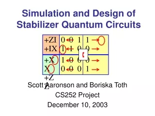
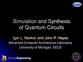
Simulation and Synthesis of Quantum Circuits. Igor L. Markov and John P. Hayes Advanced Computer Architecture Laboratory University of Michigan, EECS. Quantum Circuits Group @UMich. PIs: Prof. Igor Markov & Prof. John Hayes Postdoc: Dr. Ketan Patel (circuit testing)

E N D
Simulation and Synthesisof Quantum Circuits Igor L. Markov and John P. Hayes Advanced Computer Architecture Laboratory University of Michigan, EECS
Quantum Circuits Group @UMich • PIs: Prof. Igor Markov & Prof. John Hayes • Postdoc: Dr. Ketan Patel (circuit testing) • Graduate Student Researchers & Fellows • George Viamontes (simulation/QuIDDs) • Manoj Rajagopalan (simulation, synthesis by SA) • DoRon Motter (circuit complexity) • Smita Krishnaswamy (quantum clocks) • Parmoon Seddighrad (technology-specific opt.)
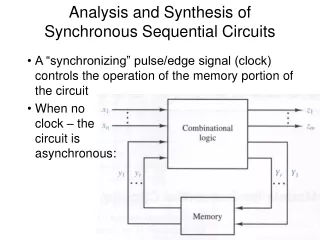
High-level Assumptions and Goals • Assumption: physicists [will] have “promising” technology prototypes • Expectation: at 20+ qubits, design complexity becomes a serious issue • Even at 20 bits, optimal logic synthesis is difficult • Our job: improve the competitiveness of prototypes and facilitate applications • Address specific design objectives and trade-offs • Discover scalable design/simulation techniques • Connect design techniques with applications • Id new types of q. circuits and new applications
Our Expertise • Computer Architecture • Electronic Design Automation / VLSI CAD • Automated Synthesis of Logic Circuits • Formal Verification • Circuit Layout • Circuit Testing • Design & analysis of algorithms/heuristics • Including Algorithm Engineering(implementation, evaluation, integration)
Design Productivity Gap • NTRS / ITRS: Design Productivity Gapis roughly 49% a year vs 21% a year • Is “quantum D. P. G.” looming ?
Fundamental Optimizations • Research in Design Automationtargets core computational obstacles • E.g., scalability in terms of runtime & QOR • Value in trying to solve “wrong” problems • Many optimization algorithmscan be easily “re-focused” • Different objectives and constraints • Example: Simulated Annealing
Research Themes (1) • “From classical to quantum” • Use classical reversible circuits as [simple] test-bed • Leverage and generalize known design techniquesfor classical circuits • Simulation-driven design • Support for quantum circuit testing • Ability to incrementally improve designsbased on results of simulations/tests • Ability to empirically evaluate quantum designsand algorithms without easily-provable properties
Research Themes (2) • New types of quantum circuits • Case-by-case automatic synthesis versus asymptotic constructions • “Real life” vs theory (cf. synthesis of classical random logic) • Empirical performance versus provable results • Separate design and simulation/test stages • Example: sequential versus combinational • New applications • Enabled by automatic synthesis • Leveraging new types of circuits, e.g., sequential
Research Topics (1) • Synthesis algorithms for classical logic as subroutines for quantum circuit synthesis • Algebraic approaches to circuit synthesis • E.g., abstract and computational group theory • Matrix factorizations: QR, ILU, CS and KAK • Special-case synthesis, e.g., Grover oracles • Generic quantum circuit synthesis and reduction • Dynamic programming • Annealing and other heuristics
Research Topics (2) • Automatic error correction during synthesis • Efficient simulation of quantum circuits • Graph-theoretical algorithms based on common arithmetic sub-expressions (QUIDDs) • New types of quantum circuits • Quantum clocks and other sequential circuits • New [and old] applications • Quantum optimization algorithms (heuristics) • Memory-savvy versions of known algorithms
Remaining Part Of The Talk • Synthesis of Reversible Logic Circuitsand Applications to Grover’s Search • Synthesis of Quantum Circuitsby Simulated Annealing • High-performance Simulationof Quantum Circuits using QuIDDs
Optimal Synthesis ofReversible Logic Circuits Vivek V. Shende, Aditya K. Prasad, Igor L. Markov and John P. Hayes Advanced Computer Architecture Laboratory University of Michigan, EECS
Outline • Motivation • Real-world Applications • Asymptotically Zero-Energy circuits • Links to Quantum Computation • Background • Theoretical Results • Synthesis of Optimal Circuits • An Application to Quantum Computing
Real-world Applications • Many inherently reversible applications • Info. is re-coded, but none is lost or added • Digital signal processing • Cryptography • Communications • Computer graphics • Network congestion modeling
Links to Quantum Computation • Quantum operations are all reversible • Every (classical) reversible circuit may be implemented in quantum technology, with overhead • “Pseudo-classical” subroutines of quantum algos • Can be implemented in classical reversible logic circuits • Grover’ssearch :
Outline • Motivation • Background • Reversibility • Permutations • Known Facts • Theoretical Results • Synthesis of Optimal Circuits • An Application to Quantum Computing
Reversibility in Logic Gates • Definition: reversible logic gate • #input wires = #output wires • Permutes the set of input values • Examples • Inverter • 2-input, 2-output SWAP (S) gate • k-CNOT gate • (k+1)-inputs and (k+1)-outputs • Values on the first k wires are unchanged • The last value is flipped if the first k were all 1
Reversibility in Logic Circuits • Definition:A combinational logic circuit is reversible iff • It contains only reversible gates • It has no fan-out • It is acyclic as a directed multi-graph • Theorem:A reversible circuit must • Have as many input wires as output wires • Permute the set of input values
A Reversible Circuit and Truth Table Equivalent to a single CNOT gate
Circuit Equivalences • Circuit equivalences: useful in synthesis • More will be shown later
Reversible Circuits & Permutations • A reversible gate (or circuit) with n inputs and n outputs has • 2n possible input values • 2n possible output values • The function it computes on this set must, by definition, be a permutation • The set of such permutations is called S2n
Basic Facts About Permutations • Permutations are multiplied by first applying one, then the other • example: (1,2)◦(2,3) = (1,3,2) • A transposition • permutes exactly two elements • does not change any others • Every permutation can be writtenas a product of transpositions
Even Permutations • Consider all possible decompositionsof a permutation into transpositions • Theorem: The parity of the numberof transpositions is constant • Definition: Even permutations are those for which the number of transpositions is even
Known Facts • Fact 1: Consider a reversible circuit • n+1 inputs and n+1 outputs • Built from gates which have at most n inputs and n outputs • Must compute an even permutation • Fact 2: A universal gate library • CNOT, NOT, and TOFFOLI (“CNT”) • Temporary storage may be required
Outline • Motivation • Background • Theoretical Results • Zero-storage Circuits • Reversible De Morgan’s Laws • Synthesis of Optimal Circuits • An Application to Quantum Computing
Minimizing Temporary Storage • Consider CNT circuits • Theorem: even permutations computableby circuits without temporary storage • Theorem: odd permutations computablewith one line of temporary storage • Same holds for NT and CNTS circuits • The proof is constructive and may be used as a synthesis heuristic
Outline of Proof • Explicitly construct a circuit to computean arbitrary pair of disjoint transpositions (A, B) (C, D) is okay; (A, B) (B, C) is not • Pick an even permutation • Decompose it into transpositions • Will have an even number of transpositions • Pair these up, guaranteeing disjointness • Apply construction to each pair
Reversible De Morgan’s Laws (1) • De Morgan’s Laws • Can send inverters to inputs in AND/OR/NOT circuits • Reversible De Morgan’s Laws • Can send inverters to inputs in CNT circuits • Rules exist to move TOFFOLI and CNOT gates • However, it is not always possibleto push all CNOT gates to the inputs • Oddly enough, all CNOT gates can be pushed to the “middle” of the circuit
Outline • Motivation • Background • Theoretical Results • Synthesis of Optimal Circuits • Optimality • DFID Search Algorithm • Circuit Libraries • An Application to Quantum Computing
Optimality • The cost of a circuit is its gate count • Other cost functions can be considered • Definition:optimal reversible circuit • no circuit with fewer gates computes the same permutation • Theorem: a sub-circuit of an optimal circuit is optimal • Proof: otherwise, can improve the sub-circuit
The Search Procedure • Depth First Iterative Deepening Search • Checks all possible circuits of cost 1, then all possible circuits of cost 2, etc… • Avoids the memory blowup of BFS • Still finds optimal solutions (unlike DFS) • Checking circuits of cost less than n is much faster than processing cost-n circuits
Dynamic Prog + Circuit Libraries • DFID search requires a subroutine to checkall circuits of cost n, for arbitrary n • Called iteratively for 1…n • Only need to check locally optimal circuits • Build optimal circuit library bottom up by DP • Index optimal circuits by computed permutation • In practice use hash_map datastruct from STL
Empirical Circuit Synthesis • Consider all reversible functions on 3 wires(8! = 40,320 functions) • For each gate library fromN, C, T, NC, CT, NT, CNT, CNTS • Is it universal? • How many functions can it synthesize? • How long does it take to synthesize circuits? • What are largest optimal circuits?
Largest Optimal Circuits • Note that purely quantum gatescan enable smaller circuits • John A. Smolin, "Five two-bit quantum gates are sufficient to implement the quantum Fredkin gate“, PRA 53(4), 1996, pp. 2855-2856 • Q. Circuit Synthesis via the Ring Normal Form(papers by Thomas Beth and Martin Röttler)
Why Circuit Libraries? • Large speedup over straight DFID • Can be calculated from previous table • Calculated values are very large • In practice, the table cannot be generated in several hours without circuit libraries • With libraries, the table takes less than 10 min
Outline • Motivation • Background • Theoretical Results • Synthesis of Optimal Circuits • An Application to Quantum Computing • Grover’s Search • Pseudo-classical Synthesis
Quantum Circuits • Necessarily reversible • Bit-lines are now qubits • All classical reversible gates still allowed • Many other gates used as well • Circuit equivalences for reversible gatesare still valid !
Grover’s Search • A quantum algorithm for associative search(input is not sorted) • Search criterion: a classical one-output function f • Runs in time O(√N) • classical algorithms require (N ) time • Requires a subroutine that • changes the phase (sign) of all basis states (bit-strings)that match the search criterion f
Grover Oracle Circuits • To change the sign of a bit-string • Initialize a qubit to |0> - |1> • Compute the classical one-output function f • XOR the qubit with f • Whenever f =1, the sign (phase) will change • Thus, the design of Grover search circuitsfor a givenf • Is reduced to reversible synthesis • Can be solved optimally by our methods
ROM-based Circuits • Desired circuits must alter phase of basis states • All bits except one must be restored to input values • Previous work studied ROM-based circuits • Constraint: ROM qubits can never change • B. Travaglione et al., 2001, http://xxx.lanl.gov/abs/quant-ph/0109016 • Theorems + heuristic synthesis algorithms • Our work: synthesis of pseudo-classical circuits • 3 read-only “ROM” wires that can never change • 1 wire that can be changed during computation, but must be restored by end • 1 wire on which function is computed
Synthesis Algorithms Compared • Heuristic synthesis of ROM-based circuits • Proposed by Travaglione et al, 2001 • Based on XOR-sum decomposition (“XOR”) • Imposed a restriction: at most one control bit per gate can be on a ROM bit • Optimal synthesis (as described earlier) • with restriction from Travaglione (“OPT T”) • without this restriction (“OPT”)
Discussion of Empirical Results • The XOR-SUM heuristic is sub-optimal • All methods able to synthesize all 256 fns • “OPT T” can synthesize as many as “OPT”: B. Travaglione et al., 2001 • “OPT” results symmetrical about 5-6 gates • Function x requires one fewer gate than 256-x • Explanation yet to be found • “XOR” results symmetrical about 13 gates