Download
1 / 16
180 likes | 450 Vues
Explore the operation and models of synchronous circuits, Mealy vs. Moore models, state diagrams, and logic equations. Learn about transitions, advantages, and disadvantages of each model.

E N D
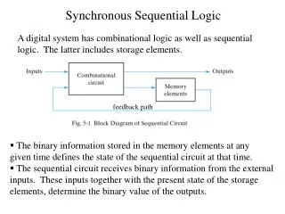
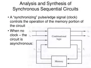
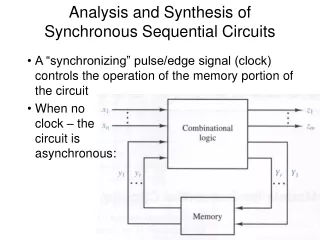
Analysis and Synthesis of Synchronous Sequential Circuits • A “synchronizing” pulse/edge signal (clock) controls the operation of the memory portion of the circuit • When noclock – thecircuit is asynchronous:
Analysis and Synthesis of Synchronous Sequential Circuits • The “state” of a synchronous sequential circuit: • All the FF/memory element outputs • Can change only upon clock transition (pulse/edge) • Two models for synchronous sequential circuits: • Mealy model • Outputs are a function of state and inputs • Moore model • Outputs are a function of state only
Mealy model • Next state (Y1,…,Yr) achieved on clock transition
Mealy model • Input (x1,…,xn), output (z1,…,zm), present state (y1,…,yr) and next state (Y1,…,Yr) are where gi and hi are Boolean functions, or in vector form
Moore model x1 xn Combinational logic Y1 Yr Memory y1 yr clock Combinational logic z1 zm
Mealy machine example • State diagram and state table • Assumes transitions Problem?
Moore machine example • State diagram and state table • Output is f(state) only • Inputs – no effect
Mealy vs. Moore • Representations can be transformed into each other • Advantages and disadvantages Mealy Moore - glitches + no glitches - problem sampling + easier to design + lesser total # states
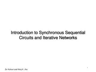
Analysis precedes synthesis • Analysis of logic diagrams of sequential circuits • Inputs, state variables, outputs, logic equations ? • Mealy or Moore type?
Analysis • Input sequence: x = 01101000
Analysis • Deriving state diagram and state table • Given circuit diagram Boolean equations • Notation: yk represents y(k t) • k = integer; t = clock period • May assign numbers to states: 0 state A; 1 state B
Analysis • Deriving state table from K-maps Map for Yk=yk+1 Map for zk
Analysis example • Synchronous sequential circuit with flip-flops • Negative edge-triggered • Inputs? • States? • Outputs? • Logic equations?
Analysis example • Timing diagram
Analysis example • State table and K-maps
Analysis example • Combining the K-maps into state table