Synchronous Sequential Logic
Synchronous Sequential Logic. Verilog provides certain syntax, which turns into synchronous sequential circuits In always statements, signals keep their old value until an event in the sensitivity list takes place


Synchronous Sequential Logic
E N D
Presentation Transcript
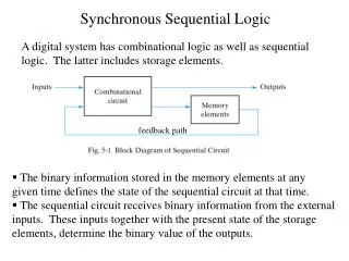
Synchronous Sequential Logic • Verilog provides certain syntax, which turns into synchronous sequential circuits • In always statements, signals keep their old value until an event in the sensitivity list takes place • Statement inside always is executed only when the event specified in the sensitivity list occurs • Note that always statement could generate combinational logic, depending on your description always @ (sensitivity list) begin statement; statement; … end
D Flip-Flop • As studied, flip-flop samples input at the edge of the clock • always @(posedgeclk) samples input at the rising edge of the clock (clk) • always @(negedgeclk) samples input at the falling edge of the clock (clk) • Any output assigned in an always statement must be declared reg • Note that a variable declared reg is not necessarily to be a registered output • We’ll see it later… • <= or = can be used inside the always statement • <= is called nonblocking assignment • = is called blocking assignment • We are going to discuss about this later module flipflop(input clk, input [3:0] d, output reg [3:0] q); always @ (posedgeclk) begin q <= d; // pronounced “q gets d” end endmodule
D Flip-Flop Simulation module Dflipflop(input clk, input [3:0] d, output reg [3:0] q); always @(posedgeclk) begin q <= d; end endmodule
D Flip-Flop with Sync and Async Reset DFF with Synchronous Reset DFF with Asynchronous Reset module ff_syncR(input clk, input reset, input [3:0] d, output reg [3:0] q); // synchronous reset // sensitively list has only clk always @(posedgeclk) begin if (reset) q <= 4'b0; else q <= d; end endmodule module ff_asyncR(input clk, input reset, input [3:0] d, output reg [3:0] q); // asynchronous reset // sensitivity list has both clk and reset always @ (posedgeclk, posedge reset) begin if (reset) q <= 4'b0; else q <= d; end endmodule
D Flip-Flop with Sync Reset module ff_syncR(input clk, input reset, input [3:0] d, output reg [3:0] q); // synchronous reset always @(posedgeclk) begin if (reset) q <= 4'b0; else q <= d; end endmodule
D Flip-Flop with Enable module ff_en(input clk, input reset, input en, input [3:0] d, output reg [3:0] q); // asynchronous reset and enable always @(posedgeclk, posedge reset) begin if (reset) q <= 4'b0; else begin if (en) q <= d; end end endmodule
D Latch • As studied, a D-latch is • transparent when the clock is high • opaque when the clock is low (retaining its old value) • Try to avoid using latches unless you have a good reason to use them because latches may transfer unwanted input (such as glitches) to output • Instead, use flip-flops module latch(input clk, input [3:0] d, output reg [3:0] q); always @ (clk, d) begin if (clk) q <= d; end endmodule
D Latch Simulation module latch(input clk, input [3:0] d, output reg [3:0] q); always @(clk, d) begin if (clk) q <= d; end endmodule
Useful Behavioral Statements • Keywords that must be inside always statements • if / else • case, casez • Again, variables assigned in an always statement must be declared as reg even if they’re not actually intended to be registers • In other words, all signals on the left side of <= and = inside always should be declared as reg
Combinational Logic using always • The always statement can also describe combinational logic (not generating flip-flops) // combinational logic using an always statement module gates(input [3:0] a, b, output reg [3:0] y1, y2, y3, y4, y5); always @ (*) // need begin/end because there is begin // more than one statement in always y1 = a & b; // AND y2 = a | b; // OR y3 = a ^ b; // XOR y4 = ~(a & b); // NAND y5 = ~(a | b); // NOR end endmodule This hardware could be described with assign statements using fewer lines of code, so it’s better to use assign statements in this case.
Combinational Logic using case What kind of circuit would it generate? module sevenseg(input [3:0] data, output reg [6:0] segments); always @(*) begin case (data) // abc_defg 0: segments = 7'b111_1110; 1: segments = 7'b011_0000; 2: segments = 7'b110_1101; 3: segments = 7'b111_1001; 4: segments = 7'b011_0011; 5: segments = 7'b101_1011; 6: segments = 7'b101_1111; 7: segments = 7'b111_0000; 8: segments = 7'b111_1111; 9: segments = 7'b111_1011; default: segments = 7'b000_0000; // required endcase end endmodule
Combinational Logic using case • In order for a case statement to imply combinational logic, all possible input combinations must be described by the HDL • Remember to use a defaultstatement when necessary, that is, when all the possible combinations are not listed in the body of the case statement • Otherwise, what kind of circuit do you think the statement would generate?
Combinational Logic using casez • The casez statement is used to describe truth tables with don’t cares • don’t cares are indicated with ?in the casez statement module priority_casez(input [3:0] a, output reg [3:0] y); always @(*) begin casez(a) // ? = don’t care 4'b1???: y = 4'b1000; // only y[3] = 1 4'b01??: y = 4'b0100; // only y[2] = 1 4'b001?: y = 4'b0010; // only y[1] = 1 4'b0001: y = 4'b0001; // only y[0] = 1 default: y = 4'b0000; endcase end endmodule
Priority Circuit Simulation module priority_casez(input [3:0] a, output reg [3:0] y); always @(*) begin casez(a) 4'b1???: y = 4'b1000; 4'b01??: y = 4'b0100; 4'b001?: y = 4'b0010; 4'b0001: y = 4'b0001; default: y = 4'b0000; endcase end endmodule
Parameterized Modules • HDLs permit variable bit widths using parameterized modules • So far, all of our modules have had fixed-width inputs and outputs • Verilog allows a #(parameter …)statement to define parameters before the inputs and outputs module mux2 #(parameter width = 8) // name and default value (input [width-1:0] d0, d1, input s, output [width-1:0] y); assign y = s ? d1 : d0; endmodule Instance with 8-bit bus width (uses default): mux2 #(8) mux1(d0, d1, s, out); Instance with 12-bit bus width: mux2 #(12) lowmux(d0, d1, s, out);
Blocking and Nonblocking Statements • In the always statement, • = indicates blocking statement • <= indicates nonblocking statement • Blocking statementsare evaluated in the order in which they appear in the code • Like one would expect in a standard programming language such as C language • Nonblockingstatementsare evaluated concurrently • All of the statements are evaluated concurrently before any of the signals on the left hand sides are updated
Blocking vs Nonblocking Example • What kinds of circuit would be generated? module sync_nonblocking (input clk, input d, output reg q); reg n1; always @(posedgeclk) begin n1 <= d; // nonblocking q <= n1; // nonblocking end endmodule module sync_blocking (input clk, input d, output reg q); reg n1; always @(posedgeclk) begin n1 = d; // blocking q = n1; // blocking end endmodule
Blocking vs Nonblocking Example 1-bit full adder + + + + S = A B Cin Cout = AB + ACin + BCin Let P = A B Let G = AB S = PCin = G + PCin Cout = AB + (A + B)Cin
Full Adder with Blocking Statements • Like a high-level language, the blocking statements are evaluated in the order they appear in the body of the module • Suppose that all the inputs and internal nodes are initially 0 • At some time later, a changes to 1 module fulladder(input a, b, cin, output reg s, cout); reg p, g; always @(*) begin p = a ^ b; // blocking g = a & b; // blocking s = p ^ cin; // blocking cout = g | (p & cin); // blocking end endmodule • p ← 1 ^ 0 = 1 • g ← 1 • 0 = 0 • s ← 1 ^ 0 = 1 • cout ← 0 + 1 • 0 = 0
Full Adder with Nonblocking Statements module fulladder(input a, b, cin, output reg s, cout); reg p, g; always @(*) begin p <= a ^ b; // nonblocking g <= a & b; // nonblocking s <= p ^ cin; // nonblocking cout <= g | (p & cin); // nonblocking end endmodule • Nonblocking statements are evaluated concurrently • Suppose that all the inputs and internal nodes are initially 0 • At some time later, a changes to 1 • p ← 1 ^ 0 = 1, g ← 1 • 0 = 0, s ← 0 ^ 0 = 0, cout← 0 + 0 • 0 = 0 • p ← 1 ^ 0 = 1, g ← 1 • 0 = 0, s ← 1 ^ 0 = 1, cout← 0 + 1 • 0 = 0 • It makes simulation slow though it synthesizes to the same hardware • Also kind of hard to figure out what the circuit is doing… This kinds of coding should be avoided
Blocking and Nonblocking Recap • Some statements generates completely different logic as shown in the flip-flop case • Some statements generates the same logic no matter which statement you use as we have seen in the full-adder case • But, it affects the simulation time • So, choose wisely which statement you have to use
Rules for Signal Assignment • Use continuous assignment statements to model simple combinational logic assign y = a & b; • Use always @(*) and blocking assignments to model more complicated combinational logicwhere the always statement is helpful • Use always @(posedgeclk) and nonblocking assignments to model synchronous sequential logic always @(posedgeclk) q <= d; // nonblocking statement • Do not make assignments to the same signal in more than one always statement or continuous assignment statement
N: 2N Decoder Example module decoder #(parameter N = 3) (input [N-1:0] a, output reg [2**N-1:0] y); always @(*) begin y = 0; y[a] = 1; end endmodule