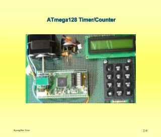
ATmega128 Timer/Counter
ATmega128 Timer/Counter. Timer Clock( 내부 또는 외부 ) 를 이용 하여 일정한 시간 주기 또는 일정 시간 후에 Event(Interrupt) 를 발생 시킨다 . Counter 외부 핀 (TOSC1, TOSC2, T1, T2, T3) 을 통해서 들어오는 Event 를 Count(Edge Detector) 한다 . ATmega128 의 Timer/Counter 4 개의 범용 타이머 / 카운트로 구성되어있다 . Timer/Counter0(8 비트 )

ATmega128 Timer/Counter
E N D
Presentation Transcript
Timer • Clock(내부 또는 외부)를 이용 하여 일정한 시간 주기 또는 일정 시간 후에 Event(Interrupt)를 발생 시킨다. • Counter • 외부 핀(TOSC1, TOSC2, T1, T2, T3)을 통해서 들어오는 Event를 Count(Edge Detector) 한다. • ATmega128의 Timer/Counter • 4개의 범용 타이머/카운트로 구성되어있다. • Timer/Counter0(8비트) • Timer/Counter1(16비트) • Timer/Counter2(8비트) • Timer/Counter3(16비트) Atmega128 Timer/Counter
기본 기능 • Single Channel Counter • Clear Timer on Compare Match (Auto Reload) • Glitch-free, Phase Correct Pulse width Modulator (PWM) • Frequency Generator • 10-bit Clock Prescaler • Overflow and Compare Match Interrupt Sources (TOV2 and OCF2) • Allows Clocking from External 32 kHz Watch Crystal Independent of the I/O Clock (Timer0 만) • External Event Counter (Timer2 만) Timer/Counter0, 2
Timer/Counter0과 2는 8비트 구조로서 유사한 OVERFOLW, PWM 기능과 제어방식을 갖는다. • Counter : 8비트(0x00 ~ 0xff) • Prescaler : 10비트(0x00 ~ 0x3ff) • Interrupt : Overflow,Output Compare Match • Timer/Counter0, 2의 Clock 입력 • Timer/Counter032.768kHz(2**15 = 32,768)의 크리스탈을 접속하는 TOSC1 및 TOSC2 단자를 가지고 있어서 RTC의 기능을 갖도록 할 수 있다. • Clock의 Pre scale 기능을 사용 하여 Counter의 Clock 주기를 다양하게 선택 할 수 있다. Timer/Counter0, 2
동작모드설정/분주비 설정 • Bit 7 : FOC0(Force Output Compare) • Non-PWM mode 에서만 동작 • 강제로 OSC0 단자에 Compare Match 신호를 출력 • Bit 3,6 : WGM01,WGM00(Waveform Generation Mode) • Bit 5,4 : COM01, COM00(Compare Match Output Mode) • Bit 2,1,0 : CS02~CS00(Clock Select) TCCR0 - Timer/Counter Control Register
Waveform Generation Mode Bit Description Compare Output Mode, non-PWM Mode
Compare Output Mode, Fast PWM Mode Compare Output Mode, Phase Correct PWM Mode
Timer/Counter 0의 8비트 Count 값을 저장하고 있는 Register TCNT0 - Timer/Counter Register OCR0 - Output Compare Register • Timer/Counter 0의 8비트 CounterTCNT0과 비교하여 OC0 단자에 출력신호를 발생하기 위한 8비트 값을 저장하고 있는 Register
Bit 3 – AS0: Asynchronous Timer/Counter0 • AS0 = 0 : 내부클럭 (clkI/O) 동기모드 • AS0 = 1 : 외부클럭 (TOSC1) 비 동기모드 • Bit 2 – TCN0UB: Timer/Counter0 Update Busy • Bit 1 – OCR0UB: Output Compare Register0 Update Busy • Bit 0 – TCR0UB: Timer/Counter Control Register0 Update Busy ASSR - Asynchronous Status Register
Bit 1 – OCIE0: Timer/Counter0 Output Compare Match Interrupt Enable • OCIE0를 Set시키면 Output Compare Match Interrupt가 활성화 된다. • Bit 0 – TOIE0: Timer/Counter0 Overflow Interrupt Enable • TOIE0를 Set시키면 Overflow Interrupt가 활성화된다. • OVF인터럽트를 사용하려면 SREG의 I=1인 상태여야 한다. TIMSK - Timer/Counter Interrupt Mask Register
Bit 1 – OCF0: Output Compare Flag 0 • TCNT0값과 OCR0값을 비교하여 이것이 같으면 이 비트가 1로 Set되면서,Output Compare Interrupt가 요청된다. 이 비트는 인터럽트 처리의 시작과 함께 0으로 Clear된다. • Bit 0 – TOV0: Timer/Counter0 Overflow Flag • 타이머/카운트에서 Overflow가 발생되면 이 비트가 1로 Set되면서 Output Compare Interrupt가 요청된다. 이 비트는 인터럽트 처리의 시작과 함께 0으로 Clear된다. TIFR - Timer/Counter Interrupt Flag Register
Bit 7 – TSM: Timer/Counter Synchronization Mode • Bit 1 – PSR0: Prescaler Reset Timer/Counter0 SFIOR - Special Function IO Register
Normal Mode • Overflow Interrupt 가 필요한 경우 사용 • 항상 Up Counter로 동작 • 0x00~0xff 범위를 반복 하여 Counting 한다. • Count 도중 Clear 없음 • MAX = 0xff 일 때 Overflow Interrupt 이 발생 • Out Compare (COMP) Interrupt는 이 Mode에서 추천 하지 않음(파형을 예상하지 못하기 때문) Timer/Counter 0의 Operation Mode
CTC Mode(Clear Timer on Compare Match Mode) • 일정한 주기 또는 주파수 분주 기능으로 사용 • Up Counter • 0x00~OCR0 구간을 반복 Counting • OCR0값과 TCNT0값이 같으면 카운트 도중 Clear • TCNT0 = OCR0 일때 Output Compare Match Interrupt 발생 • 오버프로우(OVF) 인터럽트 (MAX=OCR0값일 때 발생, COMP인터럽트와 동일하게 작동되기 때문에 추천하지 않음) Timer/Counter 0의 Operation Mode
Timer/Counter 0의 Operation Mode • CTC Mode, Timing Diagram
FAST PWM • 높은 주파수의 PWM 파형발생이 필요할 때 사용 • 상향카운터 (Single-Slope Operation) • 0x00~0xFF 계수 동작 반복 • TCNT0과 OCR0의 Compare Match되면 OC0에 LOW출력(COM0 1:0 = 2) • 0xFF → 0x00 : Overflow 발생 시 OC0에 HIGH출력(COM 1:0 = 2) Timer/Counter 0의 Operation Mode
Timer/Counter 0의 Operation Mode • Fast PWM Mode, Timing Diagram
Phase Correct PWM • 높은 분해능의 PWM출력 파형을 발생하는데 사용 • 상향카운터 0x00 → 0xFF • 하향카운터 0xFF → 0x00 • 0x00 ~ 0xFF ~ 0x00 계수 동작 반복 • 상향카운터 Compare Match >> OC0 = 0출력(COM1:0=2) • 하향카운터 Compare Match >> OC0 = 1출력(COM1:0=2) Timer/Counter 0의 Operation Mode
Timer/Counter 0의 Operation Mode • Phase Correct PWM Mode, Timing Diagram
Timer0 응용 프로그램 예 • cho_key_debounce_timer0 • cho_keypad_basic_timer0 • cho_input_capture_pulse_width_measure • cho_event_counter