ECE 654: Plasma Processing (tentative)
ECE 654: Plasma Processing (tentative). Week 1-3: Introduction, dc Discharges, PDP/BLU Week 4-6: Waves, Transport, CCrf Disch. Week 7-9: ICP, Collisions Week 10-12: Global Modeling, NL Sheath Week 13-15: Etching, Diagnostics. Plasma Application Modeling @ POSTECH.

ECE 654: Plasma Processing (tentative)
E N D
Presentation Transcript
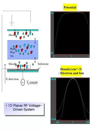
ECE 654: Plasma Processing(tentative) • Week 1-3: Introduction, dc Discharges, PDP/BLU • Week 4-6: Waves, Transport, CCrf Disch. • Week 7-9: ICP, Collisions • Week 10-12: Global Modeling, NL Sheath • Week 13-15: Etching, Diagnostics
Plasma Application Modeling@ POSTECH Introduction of PDP Energy Flow in PDP cell 5 lm/W 1.5~2 lm/W Present PDPs Future PDPs High efficiency cell structure with low power consumption should be needed
Radiation transport in PDP Striation phenomenon (a) t = 0.40s anode anode cathode cathode (b) t = 0.70s (c) t = 1.00s Xe ion Electron Ion angle distribution on MgO Pulse simulation Investigation of Plasma Characteristics in a PDP Cell
Plasma Application Modeling@ POSTECH 3-D Fluid Code for PDP (FL3P) y We can consider the 3-D effects of barrier rib and electrode shape. Examples of electrode shape x z y x z
arc Townsend R s.s. Ch.14. DC Discharge §14.1 (p.451) Def of Various Regimes of a dc normal glow PDP: neg glow only (~1lm/w) fluores. light: pos. glow (~70lm/w) §14.2 Positive Glow Column (s.s.) 1-D analysis ( ch.5 & same as for rf discharge. ch.10) (1)Te Improved eq. For Te (2) cyl. Eq. for Te 2.405
(Newtonian eqs) Ch.2 ◎Kinetic Eqs & Equil.Maxwell Distr Distribution Function as averaged quantity from truly kinetic : A bit more continuum(averaged, coarse-grained) Defined only on phase space meshes Fluid: n(xi,t) define only on spatial meshes Boltzmann eq with an unclosed form of collision term L&L(2.3.3),Golant(3.17) -Kinetic Simulations •Mol-Dynamics Sim •Particle Sim(P-P) •PIC (PIC/MCC;P3M;P-M) •Vlasov sim(Boltzmann Sim)
Plasma Application Modeling@ POSTECH Angle and energy dist. - Xe 5%, 300 Torr 12
2nd bunch 1st bunch B 13V A Anode region Plasma Application Modeling@ POSTECH Striation issue (2) Xe 10% - Ne 90% Xe+ Ne+ - Point B becomes the center region of next striation hump. - Potential difference between points A and B is about 13V. El
Strong coupled ( P.E >> K.E. ) matter ( ie, solid ) Weakly coupled matter (ie, plasma, K.E.>>P.E. ) -Derivation of the Debye-shielded Potential
◎ T (eV) vs T(K) ◎ mmHg
EEDF Comparison for a Small-Gap CCP • Langmuir • Probe by Godyak J = 2.65 • Thomson Scattering by Elsabbagh, Muraoka • Using PIC-MCC • Simulation J = 3.8 J = 3.8 mA/cm2
Fluid Eqs. & MHD Eqs. MHD eqs. 2-fl. Eq. -Fluid eqs.from Kinetic Eq. Taking 0th moment of Eq. of Continuity 1st moment of Eq. of motion 2nd moment of Energy balance eq.
◎Saha eq -F.chen: (T in °K, n in m-3) -Golant: (T in eV, n in cm-3) -Boulos: -Boltzmann statistics Thus
4mm Capillary tube, 15psi H2 4mm Capillary tube, 15psi H2 4mm capillary tube, 15psi H2 After Neutral density filter
L&L ch. 14 -Lamps, plasma display, BLU -Magnetron sputter, hollow cathode, PVD JK LEE (Spring, 2007)
14.3 Cathode Sheath : Vac. Breakdown ; Paschen Law(14.3.9) Question:what’s needed to breakdown Ar? at Pn = 1Torr, d =1 cm vb brkdn Ar Meaning ofbrkdn ne • Townsend 1st Ionization Coeff. t ne p ne(z) i e z • Breakdown or No-Breakdown (in simulation) • Ni or Ne increasing exponentially (faster than linear in t) • Ni > Nthr. ~ • The profile shapes of & Ni E(z)/p Non-unif. ?
bus electrode Front panel dielectric ITO electrode MgO layer phosphors barrier address electrode Back panel Plasma Application Modeling@ POSTECH Necessity of Simulation Research Objective Requirement of Simulation Using various simulation codes (fluid, kinetic and hybrid codes) Limitation of experimental measurement in understanding the plasma dynamics (wall charge, potential, and excited species density distributions) Suggestion of new PDP cell and pulse with high efficiency and its optimization - Small system size (a few hundred m) Study of plasma discharge characteristics - Short discharge time (less than 1s) Comparison with experimental measurement Estimation and leading of research direction 2-D Modeling of PDP cell using numerical simulation codes 3-D
Plasma Application Modeling@ POSTECH Diagnostics of Fluid Simulation Density distributions Light distributions cathode anode Wall charge distributions Potential distributions
80 % 90 % conventional model 150 % 110 % conventional model conventional model New PDP Cell Structures using Simulation
Plasma Application Modeling@ POSTECH Session 1 Flat fluorescent lamp for LCD backlight
Plasma Application Modeling@ POSTECH Display devices Transmissive device Emissive device TFT-LCDs need back-light unit (BLU) for light source!
Mercury-Free Lamps CCFL Qauntity (arbitary) Present EEFL Home LCD TV Flat Lamp EEFL By G.S.CHO 1998 2000 2002 2004 2006 2008 2010 [Year] Lamp (LCD) Industry Forecast (GS Cho)
e e e e e e e • Hot Cathode F.L. : general lighting, long & large tubing • Cold Cathode F.L. : LCD-BLU, Neon-Sign • HID Lamp : Arc-Discharge : Outdoor, Automobile • Electrode-less Lamps • Inductive Coupled Discharge : QL lamp, Endura lamp (High Power, High Fr. Discharge) • Capacitive Coupled Discharge : External Electrode F.L.(Low frequency)- Possibility of a new lamp. Thermionic electron emission (large tube, complex driving methods, short life) Ion-Induced electron emission (small & thin tube, simple driving, long life) Wall electron emission ( simple manufacturing & driving, long life) GS Cho
2006. Plasma Application Modeling POSTECH LOGO LCD Backlight (Flat Fluorescent Lamp) Y.S. Seo, S.M. Lee and J.K. Lee Department of Electronic and Electrical Engineering, POSTECH
reference case4 Xe* density distribution evolution (I) (e) (b) (c) (f) (c) (d) (a) (a) t = 200.1s Max. density 2.01E11 Max. density 6.68E11 (b) t = 200.25s Max. density 1.56E12 Max. density 6.42E12
Plasma Application Modeling, POSTECH Simulation results (I) (b) t = 200.25s Max. density 6.43E12 (e) t = 202.05s Max. density 6.41E12 214% 168%
1.0mm 10mm 0.5mm 2mm 0.5mm 1.2mm 1mm 1.5mm 1.5mm 1mm 5mm Plasma Application Modeling, POSTECH Simulation results (II) 228% 214% 168%
Plasma Application Modeling Group POSTECH Area for 2-D simulation Stainless-steel Substrate Antenna LAPS Equipment(1,020mm 830mm 437mm) 8th generation flat panel (2.2X2.5 m); 7th (1.87X2.2 m)
• μ ,
• SUMMARY OF PLASMA WAVES (1) BO = 0 uncoupled cs IAW (2) BO = 0 : coupled cs~vi IA IA : hot electron –shield ion - wave (3) Bo = 0 vA UH wLH=210 R vA wL 200 L C EC LH 4 4 W IC MS 0.1 SA