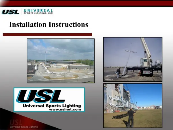
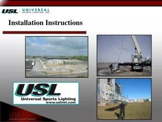
Installation Instructions
Installation Instructions. Delivery. Light fixtures, mounting structures and electrical components ship together Poles ship on a separate truck. Field Installation. These Instructions are to be used as a general guideline. It is up to the contractor to determine their

Installation Instructions
E N D
Presentation Transcript
Delivery Light fixtures, mounting structures and electrical components ship together Poles ship on a separate truck
Field Installation These Instructions are to be used as a general guideline. It is up to the contractor to determine their own installation method 5 Step Process Everything Supplied by USL CE Fixture Mounting Structure Electrical Drop Cables Electrical Enclosure Pole Systems
CE Fixture Identification Both Integral and Remote Ballast Systems Utilize the Same Optical Assembly and Share the Same Mounting Procedure Up to 12 opticals ship in a large magna pack. Outside of magna pack is labeled fixture number and mounting structure. Each optical assembly is labeled for specific location – pole designation and fixture number on mounting structure.
CE Fixture Optical Mounting Optical has Plug Connection and Two Bolt Mounting
Mounting Structures / Factory Wired to Power Distribution Block in Junction Box Service Basket Mounting Crossarm Mounting
Electrical Drop Cable Integral Ballast Drop Cable Remote Ballast Drop Cable
Electrical Enclosures Disconnect Enclosure Remote Ballast / Disconnect Enclosure
Pole Installation Guidelines The following pole installation steps cover direct embedded steel and concrete poles, anchor bolt and flange base poles. The information included in this document is to be used for Guideline Purposes Only. It is up to the contractor to determine their own installation method. Before erecting poles it is recommended that the mounting structure, fixtures and electrical be mounted to the poles while on the ground.
Dig the Hole The hole size and depth are determined by the size and type of pole being installed, actual site soil conditions and wind. It’s recommended that a geotechnical survey be conducted at the pole locations and a certified foundation design be provided and used in determining base requirements.
Setting Direct Burial Pole Steel Pole Direct Embedded Steel Poles can be a one, two or three section pole, depending on pole height. These poles can be set in two different ways. The pole sections can be put together while lying on the ground. The other option is to pick up and attach the base section of the pole then install the other sections over the already erected base section. Once pole is set and plumb back fill the hole with an aggregate material or concrete depending on soil conditions. Never back fill the hole with dirt.
Setting Direct Burial Pole Concrete Pole Direct Embedded Concrete Pole is a one section pole and can be picked up and set as a complete assembly. It is critical to use the pick points supplied by the pole manufacture when storing or lifting. Note: Be sure to check the pick point after reviewing weight of fixtures and mounting assembly. It is different than the pick points utilize to unload or move the pole alone. Once pole is set and plumb back fill the hole with an aggregate material or concrete depending on soil conditions. Never back fill the hole with dirt.
Setting An Anchor Bolt Pole Construct the pole foundations as shown in picture. Due to site conditions, the foundation may extend above grade. The foundation design information is determined by a structural engineer and can be supplied by Universal Sports Lighting if included in the Bill of Material and a Geotechnical report is furnished. The foundation is determined by the size of pole, the soil conditions and wind. The number of the anchor bolts is determined by the size of the pole and manufacturer of the pole. Universal Sports Lighting will supply the contractor with the information on how to orient the anchor bolts to the playing field. Care should be taken to provide the proper length of threaded anchor bolt projection.
Setting An Anchor Bolt Pole Anchor bolt poles can be a one, two or three section pole, depending on pole height. These poles can be set in two different ways. The pole sections can be put together while lying on the ground and then picked up and attached to the anchor bolts. The other option is to pick up and attach the base section of the pole to the anchor bolts and then install the other sections over the already erected base section.
Tower Assemblies – Foundations Determined Site Specific Pole Options