A 2 D
A 2 D. Group #4 Chris de Guzman Jon Gonzalez Frank Reed Jr. Paolo Ronquillo. Agenda. Project introduction and overview Milestones Design Approach Overall Specifications Sub-System presentation Administrative Plans for success Design Changes Current status vs. Milestone chart

A 2 D
E N D
Presentation Transcript
A2D Group #4 Chris de Guzman Jon Gonzalez Frank Reed Jr. Paolo Ronquillo
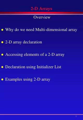
Agenda • Project introduction and overview • Milestones • Design Approach • Overall Specifications • Sub-System presentation • Administrative • Plans for success • Design Changes • Current status vs. Milestone chart • Questions?
What is it? • Digital Instrument Cluster • Replacement to a traditional analog cluster • Draws information from various sensors • Pseudo Heads Up Display • Supplements the main cluster • Touch Screen Command Center • Menu Driven UI
Goals and Objectives • The Displays should show typical vehicle data • Analog Gauges will be replaced with digital representations • Typical control knobs will be replaced with a touch screen GUI
Design Approach • Simulation • Modular • Added cost • Building materials • Sensors • Real Vehicle • Vehicle Specific • Vehicle houses project • Risk to Vehicle • Not always available
Design Approach • 3 Sub-Systems • Tied together by a main controller housing the simulation program • Allows independent development • Each sub-system is developed individually • Minimizes dependencies between systems • Project can continue to progress despite delays in other systems • Poses challenge of combining Systems
Physical Simulation of the A2D • The simulation of the dash board will be in a 4’ wide x 4’ tall x 2’ deep wooden box. Rear camera HUD Locks and windows Locks and windows Touch screen DPR Trans box Gas pedal
Specifications • The system shall be powered by a 12v battery. • The instrument cluster, HUD and touch screen shall have a 120 ° viewing angle. • The instrument cluster and touch screen shall be able to be viewed at 30 inches • The Ambient Temp sensor shall operate at a ±2.0°C accuracy. • The Compass field range shall be of at least ±2.0 gauss. • Occupant detection sensor Shall operate when no less than 10lbs. of force is detected.
Overall BD L C D Car data controller Gas pedal Rear camera Touch screen MCU Sensor controller TS controller regulator TS Display 12v PS
DESIGN & COMPONENT DECISION • Tire Pressure Monitoring System (TPMS) A2D chose Direct sensors
DESIGN & COMPONENT DECISION A2D chose battery-powered A2D chose Simulation
B) Outside Temperature Sensing System Schematic
DESIGN & COMPONENT DECISION A2D chose Digital A2D chose either TMP100 or DS1822
C) Compass Schematic HMC1002 2-Axis Magnetic Sensor h
Comparison of Function A2D chose Magnetic Compass A2D chose 2-Axis
D) Power Locking Mechanism 6 Types of Door Lock Actuators • Single wire systems • 3 Wire Negative • 3 Wire Positive • 4 Wire Reversal • 5 Wire Alternating +12V DC • Vacuum Type door lock types. The more wires there are, the more complicated a system can be. Power Lock mechanism systems depends on the manufacturer’s design and features. Every systems is made up of actuators and relay switches.
D) Power Locking Mechanism 6 Types of Door Lock Actuators • Single wire systems • 3 Wire Negative • 3 Wire Positive • 4 Wire Reversal • 5 Wire Alternating +12V DC • Vacuum Type door lock types. The more wires there are, the more complicated a system can be. Power Lock mechanism systems depends on the manufacturer’s design and features. Every systems is made up of actuators and relay switches. For simplicity
E) Vehicle Restraint System DELPHI PODS SYSTEM
Parts of Vehicle Restraint System 1) Seatbelt sensor 2)Occupant Detection sensor
Parts of Vehicle Restraint System • Seatbelt sensor • Reed Switch & Magnets 2) Occupant Detection sensor • Flex Sensor
Project Successes Sensor Systems • Most sensors are on-hand or in order • Microprocessor and development board/emulator are on hand • Started writing codes for sensors
Project difficulties • Integrating all sensors in to one Microprocessor • Lack of technical information about actual Automotive sensor systems • Sensor systems from manufacturers are EOL/Out of stock/ not available for consumer use. • Pressure sensor design on TPMS - mounting on tire valve
Heads up Display • Easier said than done! • Dual HUD/PMD design • Swiveling mirror • Easy to read • Doesn’t distract driver
LCD vs. Projector 4.06” 0.59” 1.97”
LCD vs. Projector 4.06” 0.59” 1.97” • More COST EFFECTIVE • Better suited for our space constraints • Easier to program for our purposes
Optical Design Plexiglas “HUD” Reflective film IMAGE • Cluster mode • Image viewed directly in mirror • Very sharp image Mirror Digital IC “PMD” Rotator 48” Lenses 36” LCD Side View
Optical Design Plexiglas “HUD” IMAGE Reflective film • “HUD” mode • Image projected onto ‘windshield’ • Clear image, a bit larger due to distance Mirror Digital IC “PMD” Rotator 48” Lenses 36” LCD Side View
Lenses (1) (2) • Thin lens combination (3) IMAGE Note: Not to scale
Lenses • Thor labs • Bi-convex spherical lenses • Focal length : TBD • Uncoated • Cost: ~30/lens
Optical Successes and Difficulties • Success • Resolved conflicting ideas on HUD, finalized design • Difficulties • Prototyping without having to buy parts • Reflective film • Focal Length
Touch ScreenComponent decisions • 4-wire vsCapacitive • Don’t include displays • Touch display module • 4-Wire was chosen for cost and availability • LCD vsOLED • OLED was chosen • Built in touch screen + TS controller • MCU for graphics processing • FPGA vsMCU • MCU chosen • Experience + Arduino IDE
Arduino Duemilanove For prototyping with the ATMEGA328 distributed under a Creative Commons Attribution Share-Alike 2.5 license and are available on the Arduino Web site
Pin Mapping ATMEGA328 distributed under a Creative Commons Attribution Share-Alike 2.5 license and are available on the Arduino Web site
Capturing Touch • distributed under a Creative Commons Attribution Share-Alike 2.5 license and are available on the Arduino Web site
Touch Screen Block Diagram OLED 4-Wire TS ATMega2560 5V Step Down Voltage ATMega328 User Input Sensor Inputs Fans Windows
System Success to date • Development has begun on the ATMega328 • Familiarity with Arduino IDE • All Parts have been ordered • Menu systems have been designed
What’s left? • Prototyping • Interfacing with Sensors • Testing • Final PCB design
Design Flow of the Instrument Cluster Graphic TFT LCD PIC18F4500 Sensor MCU Gas Pedal