Analyzing Two-Loop Circuits with Kirchhoff’s Rules and Animated Visuals
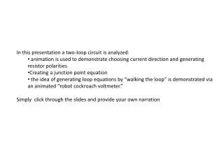
This presentation offers an engaging analysis of a two-loop electrical circuit using Kirchhoff’s Rules. It employs animation to illustrate selecting current directions and determining resistor polarities. Viewers will learn to create a junction point equation and observe the process of generating loop equations through a unique animated "robot cockroach voltmeter." The presentation encourages users to click through the slides, providing their own narration. Concepts covered include junction points, loop walks, and solving for unknown currents based on known battery EMFs and resistances.

Analyzing Two-Loop Circuits with Kirchhoff’s Rules and Animated Visuals
E N D
Presentation Transcript
In this presentation a two-loop circuit is analyzed: • animation is used to demonstrate choosing current direction and generating resistor polarities • Creating a junction point equation • the idea of generating loop equations by “walking the loop” is demonstrated via an animated “robot cockroach voltmeter.” • Simply click through the slides and provide your own narration
Kirchhoff Junction Points and Loop Walks By Leo Takahashi, The Pennsylvania State University, Beaver Campus
A circuit is constructed with known battery emfs (દ1 and દ2) and known resistances (R1, R2, and R3); we wish to know the values of the currents.
We will use Kirchhoff’s Rules as follows:At a JUNCTION POINT the currents in must equal the currents out.Around any CLOSED LOOP the sum of the potential differences (voltages) must equal zero.
- I1R1 a - I2R2 - દ2 + - I3 R1 + + + I2 દ1 Loop 2 R2 દ2 Loop 1 - - - +દ1 I1 + I2R2 R3 + - b - I3R3 V V V = 0 At a: I1 =I2 + I3 = 0
These three equations I1 = I2 + I3 દ1 – I1R1 – I2R2 = 0 I2R2 – દ2 – I3R3 = 0 can be solved for the three unknown currents.