Download

1 / 34
380 likes | 1.67k Vues
Booth Encoded Wallace Tree Multiplier Ruida Yun Nahid Rahman. Importance. Booth encoding is an effective method for multiplication of both positive and negative numbers. Wallace tree reduces the number of partial products to be added into 2 final intermediate results.

E N D
Booth Encoded Wallace Tree Multiplier Ruida Yun Nahid Rahman
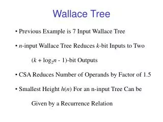
Importance • Booth encoding is an effective method for multiplication of both positive and negative numbers. • Wallace tree reduces the number of partial products to be added into 2 final intermediate results. • Carry Look-ahead Adder used to add these results to generate the final output.
Multiplication of unsigned (+ve ) numbers Multiplicand 0110 (=6) Multiplier x 1011 (=11) ----------- 0110 0110 0000 0110 ----------- 01000010 (=66) Logically can be expressed as AND operation: if MR=1 assign MD if MR=0 assign all zeros
In a 4-bit 2’s complement number system….. Multiplicand 0110 (=6) Multiplier x 1011 (=-5, signed number) ----------- 0110 0110 0000 0110 ----------- 01000010 (=66) Therefore, 8-bit result cannot be generated from 2 4- bit inputs in a signed number system.
Standard Multiplier Method Multiplicand 00000110 (=6) Multiplier x 11111011 (=-5, signed number) --------------- 00000110 00000110 00000000 00000110 00000110 00000110 00000110 ------------------------ 11100010 (=-30)
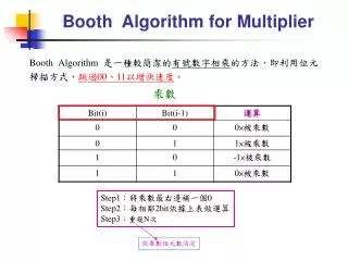
Booth’s Algorithm • Introduces a new symbol: í indicating multiplication by -1. • Multiplier is recoded in terms of 1, 0 & í. • Example: 1011 is recoded as: í10 í • AND operation changes as: if MR=1 assign MD if MR=0 assign all zeros if MR= í assign -MD
Our MR now becomes 4-bit again.. Multiplicand 0110 (=6) Multiplier x í10 í (=-5) --------------- 11111010 (-MD, sign extended) 00000000 (All zeros) 00000110 (MD, sign extended) 11111010 (-MD, sign extended) ---------------- 11100010 (=-30 , 8 bits of LSB)
Generatingí • Not possible to implement in hardware. • Therefore, done by inspecting a multiplier bit and its previous bit and generating 2 control signals x and z. • Whether the MR is í, 1 or 0, depends on these signals according to:
Tasks in Project • Generating 2’s complement of MD for –MD. • Recoding MR/generating x and z. • Generating partial products. • Sign extension. • Compressing the partial products. • Adding the final 2 operands for multiplication result.
Team Management Nahid: • Booth Encoder • Partial Product Generator Ruida: • Wallace Tree • Carry Look-ahead Adder (Smaller modules generated and tested as necessary Website: http://www.eecs.tufts.edu/~ryun01/vlsi)
Final Layout No, it’s not a gun…
Full Chip Implementation Details • Fabrication Process: AMI 0.6u C5N • Final Chip Area: 4.2mm*1.5mm • Number of PMOS: 3040 • Number of NMOS: 3040 • Total number of transistors: 6080 • Speed: 20 MHz • Power Dissipation: 15.14 mW
Drawbacks • Original Booth’s algorithm used where modified radix-4 algorithm could be used. • Ripple Carry Adder used in 2’s Complement Generator. • Area and time not optimized; very slow chip.
Goals Achieved As novice cadence users, our primary goal for this project was more of an academic nature: • We have been able to achieve completeness and overall functional accuracy in our work. • The project was foundational and served as a great learning experience. • It also provided us with valuable experience in effective collaboration, work ethics, and a very enjoyable ongoing intercommunication between different project groups.
Acknowledgements • Our research advisor Prof. Valencia Joyner for all her support. • All our new friends at the ECE department.
Thank you….. ~Ruida, Nahid.