Download
1 / 86
960 likes | 1.41k Vues
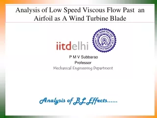
NUMERICAL AND EXPERIMENTAL ANALYSIS OF LOW REYNOLDS NUMBER FLOW AROUND AN AIRFOIL. By: Saurabh Deshpande & Abbas Electricwala Guided by: Prof. Mitesh Vegad & Mr. Sankalp Kulkarni. AIM OF PROJECT. The aim of the project is: To study the behavior of an airfoil at low Reynolds number.

E N D
NUMERICAL AND EXPERIMENTAL ANALYSIS OF LOW REYNOLDS NUMBER FLOW AROUND AN AIRFOIL By: Saurabh Deshpande & Abbas Electricwala Guided by: Prof. Mitesh Vegad & Mr. Sankalp Kulkarni
AIM OF PROJECT • The aim of the project is: • To study the behavior of an airfoil at low Reynolds number. • To understand the reasons behind the drop in performance. • To study and verify the effect of “leading edge slot” in the airfoil as a result of which performance of the airfoil increases.
THEORY • Flow over bodies: Fluid LIFT V DRAG
THEORY • Boundary layer:
THEORY • Effect of boundary layer on lift and drag: • Effective shape of airfoil changes, hence pressure drag increases and lift decreases. • Boundary layer increases fluid friction, hence shear drag increases.
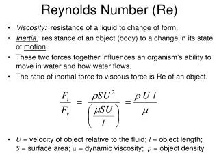
THEORY • Reynolds number: • Re = Inertia force / Viscous force = ρVL/µ • Re > 105: Flow is generally turbulent • Re < 105: Flow is generally laminar
THEORY • What happens at High Reynolds number? • Flow is turbulent hence Boundary layer thickness is small. • Therefore airfoil profile shape remains almost unaltered giving less pressure drag and high lift. • But, due to high velocities fluid friction at wall increases and shear drag increases.
THEORY • What happens at Low Reynolds number? • Flow is laminar hence Boundary layer thickness is more. • Therefore airfoil profile shape alters giving rise to higher pressure drag and low lift. • But flow velocities are very low hence shear drag is also really low.
THEORY • Flow separation • Adverse pressure gradient • Low inertia force (i.e. low Re)
THEORY • Effect of flow separation on lift and drag: • Separation occurs suddenly which gives rise to drastic decrease in lift and increase in pressure drag. • This phenomenon is called stalling.
PROJECT USEFULNESS • From the discussion we can see that it is difficult to obtain desired performance from airfoils at low Reynolds number. • Application of low Reynolds number regime? • Micro air vehicles (MAV) • Near space applications • Wind turbines • Low speed takeoff and landing of aircrafts
THEORY • Boundary Layer Control: • Suction over airfoil surface • Blowing of air over airfoil surface • Vortex creator • Trailing edge flap • Leading edge slat • Leading edge slot
PROJECT PLAN • Analysis of un-slotted airfoil at low Reynolds number using: • Numerical investigation- use of commercial CFD package • Experimental investigation- Wind tunnel testing • Followed by analysis of the same airfoil applying a Boundary layer control technique called leading edge slot: • Numerical investigation- use of commercial CFD package
SELECTION OF AIRFOIL • NACA 4 series airfoil profile • Selection of chord length • For air as the fluid, ρ= 1.225 Kg/m3 • μ= 1.7894 * 1e-05 Kg/(s*m) • Hence we get Re = 68458.7* V*l
SELECTION OF AIRFOIL • Minimum velocity obtainable: hw = 2.5 mm haρa =hwρw Therefore ha = hw *(ρw /ρa) = 2.0408 m of air column As, ha = V2/2g We get, V= 6.32 m/s
SELECTION OF AIRFOIL • Minimum chord length: • To keep the Re low chord length should be decreased. • Due to practical limitations of airfoil manufacturing chord length of 12 cm was selected. L= 0.12 m Therefore obtained Re = 5.2 * 1e+04 This Re is in the laminar flow region hence the selected chord length and dynamic head are acceptable.
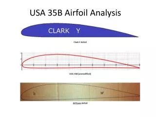
SELECTION OF AIRFOIL • NACA profile selected: • No camber to simplify the manufacturing process. • Greater the thickness of airfoil, greater the chances of flow separation. • Airfoil thickness equal to 15 % of chord length selected. • Resulting profile name and figure:
PRE PROCESSING • Characteristics of the grid: • 2-D grid • C shaped grid around airfoil • Non uniform grid with fine mesh near the airfoil • Boundary conditions: • Upstream of airfoil: Velocity inlet • Downstream of airfoil: Pressure outlet
PRE PROCESSING • Mesh around an airfoil:
PROCESSING • Flow conditions: • Incompressible • Laminar • Viscous (with constant viscosity) • Steady flow • No heat transfer between airfoil and fluid
RESULTING EQUATIONS • Continuity equation: • Momentum conservation equations: • … x-direction • … y-direction
NUMERICAL ANALYSIS • Numerical analysis was done for: • For a very low Reynolds number of 23200 and varying the angle of attack from 0, 5, 10, 15 to 20 degree. • For a Reynolds number of 52000 (to compare with experimental data) and varying the angle of attack from 0, 5, 10, 15 to 20 degree. • For angle of attack of 5 degree where Reynolds number is varied from 1e+02 to 1e+09 so that the effect of Reynolds number on lift and drag could be calculated. • For Re of 23200 at the ground level and corresponding velocity at an altitude of 10 km to check the effect of altitude on lift and drag
POST PROCESSING • Force perpendicular to airfoil (Y)= • Force parallel to airfoil (X)= + • Lift (L) = X cos θ – Y sin θ • Drag (D) = X sin θ + Y cosθ • Lift co-efficient (Cl) = L / (1/2 * ρ * A * U02 ) • Drag co-efficient (Cd) = D / (1/2 * ρ * A * U02 ) • Airfoil performance indicated by: Cl/Cd
RESULTS OBTAINED FOR UN-SLOTTED AIRFOIL USING NUMERICAL INVESTIGATION
EFFECT OF REYNOLDS NUMBER AoA = 5 degree
EFFECT OF REYNOLDS NUMBER AoA = 5 degree
EFFECT OF REYNOLDS NUMBER Re= 105 AoA = 5 degree
PERFORMANCE AT LOW REYNOLDS NUMBER Stall angle Re = 23200
PERFORMANCE AT LOW REYNOLDS NUMBER Re = 23200
PERFORMANCE AT LOW REYNOLDS NUMBER Optimum performance Re = 23200
EFFECT OF BOUNDARY LAYER Re = 23200
EFFECT OF BOUNDARY LAYER Re = 23200
EFFECT OF ALTITUDE (V= 0.33889 m/s) • For velocity 0.3389 m/s • At altitude 0 km from ground: Re= 23,200 • At altitude 10 km from ground: Re= 9,613 • As altitude increases, Reynolds number decreases and hence performance drops. • Cl/Cd at the optimum performance angle drops by 9.52% as altitude increases to 10 km.
VELOCITY VECTOR PLOTS- 0 DEGREE AoA Re = 23200
PRESSURE CONTOURS- 0 DEGREE AoA Re = 23200
VELOCITY VECTOR PLOTS- 5 DEGREE AoA Re = 23200
PRESSURE CONTOURS- 5 DEGREE AoA Re = 23200
VELOCITY VECTOR PLOTS- 20 DEGREE AoA Point of flow separation Re = 23200
PRESSURE CONTOURS- 20 DEGREE AoA Wake region Re = 23200
PURPOSE OF EXPERIMENTATION • To verify the results obtained by the numerical investigation • Verification has been done by comparing the graphs of “Cl/CdvsAoA” obtained by numerical and experimental investigation.
EXPERIMENTATION OVERVIEW • To calculate lift and drag forces, pressure distribution around an airfoil needs to known. • This can be achieved by providing pressure taps on the surface of an airfoil and connecting them with the pitot tube. • The airfoil should be hollow to accommodate the pressure taps.
FABRICATION OF AIRFOIL • Manufactured in college workshop • Design considerations: • 3 wooden sections joined by iron rods to form the frame. • Plastic sheet used to cover the frame. • Pressure taps provided to measure static pressure distribution around airfoil.
FABRICATION OF AIRFOIL • AutoCAD drawings of three wooden sections • Mid section: • Side section with hollow pin: • Side section with the threaded bolt: