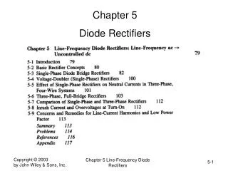
Chapter 5 Diode Rectifiers
Chapter 5 Diode Rectifiers. Basic rectifier concepts Single-Phase diode bridge rectifiers Voltage-Doubler rectifiers. Diode Rectifier Block Diagram. Uncontrolled utility interface (ac to dc). A Simple Circuit ( R Load). Resistive load. A Simple Circuit ( R-L Load).

Chapter 5 Diode Rectifiers
E N D
Presentation Transcript
Chapter 5 Diode Rectifiers • Basic rectifier concepts • Single-Phase diode bridge rectifiers • Voltage-Doubler rectifiers Chapter 5 Line-Frequency Diode Rectifiers
Diode Rectifier Block Diagram • Uncontrolled utility interface (ac to dc) Chapter 5 Line-Frequency Diode Rectifiers
A Simple Circuit (R Load) • Resistive load Chapter 5 Line-Frequency Diode Rectifiers
A Simple Circuit (R-L Load) • Current continues to flows for a while even after the input voltage has gone negative Chapter 5 Line-Frequency Diode Rectifiers
A Simple Circuit (R-L Load) Chapter 5 Line-Frequency Diode Rectifiers
A Simple Circuit (Load has a dc back-emf) • Current begins to flow when the input voltage exceeds the dc back-emf • Current continues to flows for a while even after the input voltage has gone below the dc back-emf Chapter 5 Line-Frequency Diode Rectifiers
Single-Phase Diode Rectifier Bridge • Large capacitor at the dc output for filtering and energy storage Chapter 5 Line-Frequency Diode Rectifiers
Diode-Rectifier Bridge Analysis R load I load • Two simple (idealized) cases to begin with: (a) R load (b) current load Chapter 5 Line-Frequency Diode Rectifiers
Waveforms with a purely resistive load at the output Chapter 5 Line-Frequency Diode Rectifiers
Diode-Rectifier Bridge Input Current THD=48.43% DPF=1.0PF=DPF x Is1/Is=0.9 • Idealized case with a purely dc output current Chapter 5 Line-Frequency Diode Rectifiers
Diode-Rectifier Analysis with AC-Side Inductance • Output current is assumed to be purely dc Chapter 5 Line-Frequency Diode Rectifiers
Understanding Current Commutation • Assuming inductance to be zero Chapter 5 Line-Frequency Diode Rectifiers
Understanding Current Commutation #2 • Assuming inductance to be zero Chapter 5 Line-Frequency Diode Rectifiers
Understanding Current Commutation #3 • Assuming inductance to be zero Chapter 5 Line-Frequency Diode Rectifiers
Understanding Current Commutation #4 • Inductance is included Chapter 5 Line-Frequency Diode Rectifiers
Current Commutation Waveforms vd u vL Id is Chapter 5 Line-Frequency Diode Rectifiers
Current Commutation Waveforms Chapter 5 Line-Frequency Diode Rectifiers
Average voltage <Vd> When L=0 With finite L Reduction in average output voltage Chapter 5 Line-Frequency Diode Rectifiers
Current Commutation in Full-Bridge Rectifier Chapter 5 Line-Frequency Diode Rectifiers
Current Commutation in Full-Bridge Rectifier Chapter 5 Line-Frequency Diode Rectifiers
Current Commutation Waveforms Chapter 5 Line-Frequency Diode Rectifiers
Average voltage <Vd> When L=0 With finite L Reduction in average output voltage Chapter 5 Line-Frequency Diode Rectifiers
Conclusions • Average output voltage drops with • increased current • increased frequency • Increased L • Load Regulation is a major consideration in most rectifier systems because • voltage changes with load (IL) Chapter 5 Line-Frequency Diode Rectifiers
Diode-Rectifier with a Capacitor Filter • Power electronics load is represented by an equivalent load resistance Chapter 5 Line-Frequency Diode Rectifiers
Diode-Bridge Rectifier: Waveforms • Analysis using PSpice Chapter 5 Line-Frequency Diode Rectifiers
Voltage Doubler Rectifier input input • In 115-V position, one capacitor at-a-time is charged from the input. Chapter 5 Line-Frequency Diode Rectifiers