Download
1 / 14
140 likes | 310 Vues
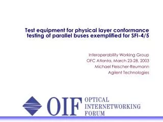
Test equipment for physical layer conformance testing of parallel buses exemplified for SFI-4/5. Interoperability Working Group OFC Atlanta, March 23-28, 2003 Michael Fleischer-Reumann Agilent Technologies. Agenda. Motivation

E N D
Test equipment for physical layer conformance testing of parallel buses exemplified for SFI-4/5 Interoperability Working Group OFC Atlanta, March 23-28, 2003 Michael Fleischer-Reumann Agilent Technologies
Agenda • Motivation • Location within the system architecture of parallel buses specified by OIF and their architectural parameters • General measurement setup to prove SFI-4/5 compliance • Focus on timing measurements on SFI-4/5 I/OsSFI-4 output timingSFI-5 output timingSFI-4/5 input timing • Specific SFI-5 - item: Jitter and Wander (common and relative) • Parallel test equipment: Agilent ParBERT 81250 Platform • Summary
Motivation • Interoperability – how to demonstrate it? • Let modules of different vendors work together as demonstrated at the booth • Interoperability – how to assure it? • Let modules of different vendors work together under corner cases or marginal conditions! • But usually those can not be achieved with regular modules! • Consequently use test equipment • for input ports: to generate corner cases according to specifications (e.g. marginal input timing) • for output ports: check that specified limits are met to measure the compliance with specifications published in implementation agreements
Focus of this presentation System architecture and location of different buses/standards TDMfabric Serdes/PHY SPI-3, SPI-4-1/2, SPI-5,TFI-5 Framer FEC SFI-4-1/2, SFI-5 SFI-4-1/2, SFI-5 VSR-4-01..05 VSR-5
DCA Parallel BERT PG mux/ TX Serial BERT ED O/E DUT e.g. 300pin MSA Parallel BERT ED RX/ de-mux Serial BERT PG E/O general measurement setups to prove SFI-4/5 compliance SFI-4/5 side Serial side ParBERT 675M/3.35G generators stimulate DUT on SFI-4/5 bus varying parameters (e.g timing) to emulate critical corner cases on serial side DUT’s functionality (BER=0) or performance (eye mask, jitter) is monitored with ParBERT 10.8G/45G analyzer or with DCA ParBERT 675M/ 3.35G Analyzers monitor DUT’s functionality (BER=0, RXDSC=ok) on SFI-4/5 andmeasure compliance for skew/jitter with timing measurement or signal quality with fast eye mask or eye diagram measurement. ParBERT 10.8/45G generators stimulates DUT on serial side (electrical or optical) with nominal signals Direct Input to Output: DItO electrical optical Loopback or Back to Back (B2B)
Focus on: Output Timing Measurements (SFI-4) • Specification • Data valid window: UI-400psor ts/th=+/-200ps • Measurements and results • BERT-scan:ts/th value and pass/fail, skew between channels • Fast eye mask:user defined eye mask pass/fail • Eye diagram
Focus on: Output Timing Measurements (SFI-5) • Specification • Maximum skew between data and deskew channels: 2UI (at DUT output), 5(.65)UI after “channel” • Measurements and results • Fast eye mask w/ user defined points => pass/fail • Eye diagram • BERT-scan • data capturew/ automaticsample pointadjust =>skew between channels and Rx/TxDSC
Focus on: Input Timing Measurements (SFI-4/SFI-5) • Specifications • SFI-4: Ts/th +/-300ps • SFI-5: skew < 5(.65)UI • Measurement • set input timing to corner cases to verify conformance and check correct functionality or • vary input timing until functional failure appears to characterize valid input timing range • BUT: How to check correct functionality/ failure? • Check waveform on serial side? • Check BER=0 on serial side! • Loop back and check BER=0 on parallel side!
inverted bit jammed bit delayed bit failure free Functional verification by waveform check only? Only one waveform stems from a failure free serializer or mux!!
Specific item for SFI-5: HF jitter tolerance Noise Source Pulse or PRBS generator Eye opening at receiver 1 : 2 power adder Jitter modulation inputs two ranges: 50 & 500ps/V DJ, (RJ) and TJ are user definable through variable amplitude and frequency simple adjustment to different data rates ParBERT Generators DUT
range 2: <1.3UI, >120kHz ParBERT running at 2.5Gb/s modulate generators with slightly different frequencies Specific item for SFI-5: Common plus relative Wander range 1: >1.3UI, <120kHz • ParBERT in ext. clock mode • central clock modulated by external signal generator Test in two ranges with different setups at discrete frequencies 10MHz ref f1+Df f1 UI wander 10.65 ParBERT Generators common MUX 1.3 relative 0.1 f
ParBERT 81250 PlatformProduct offering E4875A ParBERT Software Suit E4875A includes GUI, Measurement Software, SFI-5 and 10GbE Post-Processing Tools Q-factor and timing analysis incl. RJ/DJ separation Software Modules N4872A 13.5 Gb/s Generator Module E4805B/08A Standard/ High Performance Clock Module E4832A 675 Mb/s Module E4810A 3.35 Gb/s Electrical/Optical Generator Module E4811A 3.35 Gb/s Optical/Electrical Analyzer Module E4866A 10.8 Gb/s Generator Module E4861A 2.7 Gb/s Module E4861B 3.35 Gb/s Module E4867A 10.8 Gb/s Analyzer Module N4873A 13.5 Gb/s Analyzer Module E4896A 45 Gb/s Pattern Generator Bundle E4867A 45 Gb/s Error Detector Bundle E4883A Lightwave Transmitter Module E4882A Lightwave Receiver Module E4884A High Performance Lightwave Option Front Ends E4838A 675 Mb/s Generator E4835A 675 Mb/s Analyzer E4862A/64A/63A/65A 2.7/1.6 Gb/s Generator/Analyzer E4862B/63B 3.35 Gb/s Generator/Analyzer 675 Mb/s 2.7/1.6 Gb/s 10.8 Gb/s 13.5 Gb/s 45 Gb/s 3.35 Gb/s
Summary • Variety of bus architectures requires versatile test equipment • Absolutely necessary to stimulate all relevant signals of the bus (data + clock + dsc + ...) w/ the ability to vary signal parameters and data content • to adopt to different buses and • to create corner cases /stress conditions • Necessary to verify correct functionality by more than a waveform measurement • either on serial side upon Direct Input to Output measurement w/ Serial BERT or single BERT ED channel • on parallel side after loop-back-test (w/ parallel analysis equipment i.e. parallel BERT ED) • Ability of parallel BERT ED (ParBERT) to measure on all (data) channels simultaneously lowers test time significantly