Development of the Optical Autocovariance Wind Lidar (OAWL) Instrument Design for ISS
This presentation summarizes the 2012 study of the Optical Autocovariance Wind Lidar (OAWL) instrument conducted by Ball Aerospace at NASA's Goddard Instrument Design Lab (IDL). Funded by the NASA Earth Science Technology Office (ESTO), the study aimed to demonstrate that the OAWL can fulfill the requirements of a wind lidar mission using aerosol backscatter at 355 nm wavelength. The IDL confirmed a feasible design with components at high technology readiness levels, meeting the necessary volume, mass, power, and thermal budgets for a long-duration ISS mission.

Development of the Optical Autocovariance Wind Lidar (OAWL) Instrument Design for ISS
E N D
Presentation Transcript
Sara Tucker, Carl Weimer, Tom Delker, Chris Seckar, Mike Adkins – Ball Aerospace & Technologies Corp. Funding provided by the NASA Earth Science Technology Office (ESTO)ESTO Representatives at the IDL: Michael Pasciuto & Keith Murray Optical Autocovariance Wind Lidar (OAWL) Instrument Design Lab (IDL) Study: 25-29 June 2012Final Output Presentation
Summary • This presentation contains information about the 2012 run of the Ball-Aerospace Optical Autocovariance Wind Lidar (OAWL) Instrument design concept through the Goddard Instrument Design Lab (IDL) • The OAWL IDL run, funded by ESTO, was performed as part of the effort to demonstrate that the OAWL Instrument can meet the requirements of the aerosol component of a wind lidar mission – using the same 355 nm wavelength proposed for molecular systems. • The IDL concluded that the baseline OAWL system design is feasible with many components at high TRL, and that the system can fit within the volume, mass, power, and thermal budgets of a JEM-EF module on the ISS with >80% reliability for a 1-year requirement, 2-year goal. Ball Aerospace & Technologies Corp. and NASA Earth Science & Technology Office OAWL 2012 Instrument Design Lab (IDL) Study Results - Presented at the Working Group on Space-based Wind Lidar, 17 October 2012
OAWL Instrument Design Lab (IDL) The Optical Autocovariance Wind Lidar (OAWL) is a Doppler Wind lidar designed to measure winds from aerosol backscatter at 355 nm wavelength.* *Adding 532 nm is an option for High Spectral Resolution Lidar + 532 nm winds, but not used in this IDL IDL ObjectiveThe Optical Autocovariance Wind Lidar (OAWL) IDL study objective is to generate a GSFC-IDL-vetted blueprint and cost scope (within an Earth-Venture- cost cap) for an OAWL mission on the ISS thereby maturing the optical, electrical, structural, thermal, and software designs for a space-based OAWL. IDL FundingThe OAWL IDL was funded by the NASA Earth Science Technology Office (ESTO). Ball Aerospace internal investments were used to develop the JEM-EF lidar concepts (previous investment) and to develop the OAWL radiometric model used for trade studies. IDL TimelineThe OAWL IDL (at Goddard) took place 25-29 June 2012. Ball Aerospace & Technologies Corp. and NASA Earth Science & Technology Office OAWL 2012 Instrument Design Lab (IDL) Study Results - Presented at the Working Group on Space-based Wind Lidar, 17 October 2012
OAWL IDL 2012 Study Participants • Study week: 25-29 June 2012 • Funded by NASA Earth Science Technology Office (ESTO) • Ball team at the IDL: • Sara Tucker (PI) • Tom Delker • Carl Weimer • ESTO • Mike Pasciuto • Keith Murray • ESTO visitors • IDL Team • Team Lead: Jennifer Bracken • Attitude Determination: Kong Ha • Contamination: Tom Riley • Costing: Sharon Seipel, Sanjay Verma • Detectors: Carl Kotecki • Electrical: Paul Earle • Flight Software: KequanLuu • Lasers: Barry Coyle • Mechanical Designer: Dave Palace • Mechanical Systems: John Crow • Mechanisms: Dick McBirney • Optics: Peter Hill, Bert Pasquale • Reliability: AronBrall • Structural (TBD): Jeff Bolognese • Systems: Ed Aguayo & Martha Chu Ball Aerospace & Technologies Corp. and NASA Earth Science & Technology Office OAWL 2012 Instrument Design Lab (IDL) Study Results - Presented at the Working Group on Space-based Wind Lidar, 17 October 2012
OAWL IDL Study Summary • Ball Aerospace went into the study with a fairly mature design concept for the OAWL system in a JEM-EF module. • The IDL engineering experts performed thorough reviews of this design (in their individual areas of expertise, and as a team) and vetted all of the components. They found no tall poles in the component technology or design. • The IDL then performed some repackaging of the Ball design, recommended alternatives for some minor components, and added an initial design concept for thermal control. • Based on the IDL experts’ conclusions for component TRLs, the IDL then performed a parametric costing analysis using Price-H for hardware and SEER-SEM for software Ball Aerospace & Technologies Corp. and NASA Earth Science & Technology Office OAWL 2012 Instrument Design Lab (IDL) Study Results - Presented at the Working Group on Space-based Wind Lidar, 17 October 2012
Systems Overview & Science Requirements Ball Aerospace & Technologies Corp. and NASA Earth Science & Technology Office OAWL 2012 Instrument Design Lab (IDL) Study Results - Presented at the Working Group on Space-based Wind Lidar, 17 October 2012
Performance Requirements • The OAWL Science Requirements were designed to meet or exceed the aerosol portion of the 3D-Winds mission concept requirements (which are subject to change) – The OAWL 2012 IDL did not include a molecular channel. • Latest 3D-Winds requirements • NOTE: OAWL maximum horizontal speed detection is based on etalon filter bandwidth constraints & pointing/station-speed knowledge and NOT on detection bandwidth as seen in coherent systems. Ball Aerospace & Technologies Corp. and NASA Earth Science & Technology Office OAWL 2012 Instrument Design Lab (IDL) Study Results - Presented at the Working Group on Space-based Wind Lidar, 17 October 2012
Pointing Angles for OAWL on JEM-EF • JEM-EF chosen for mass/power, cooling availability • Beams point off-nadir 40º inboard • Forward + Aft views separated by 90º (±45º from cross-track) Ball Aerospace & Technologies Corp. and NASA Earth Science & Technology Office OAWL 2012 Instrument Design Lab (IDL) Study Results - Presented at the Working Group on Space-based Wind Lidar, 17 October 2012
OAWL ISS Coverage (24 hours) • Green = ground track • Yellow = coverage (observation) swath Ball Aerospace & Technologies Corp. and NASA Earth Science & Technology Office OAWL 2012 Instrument Design Lab (IDL) Study Results - Presented at the Working Group on Space-based Wind Lidar, 17 October 2012
OAWL IDL: Fundamental Instrument limits(JEM-EF) - and requirements for SNR *limits set by JEM-EF module Ball Aerospace & Technologies Corp. and NASA Earth Science & Technology Office OAWL 2012 Instrument Design Lab (IDL) Study Results - Presented at the Working Group on Space-based Wind Lidar, 17 October 2012
OAWL IDL Block Diagram Valve Actuator (x2) Ball Aerospace & Technologies Corp. and NASA Earth Science & Technology Office OAWL 2012 Instrument Design Lab (IDL) Study Results - Presented at the Working Group on Space-based Wind Lidar, 17 October 2012
Top Level Summary of Conceptual System (IDL Output) These parameters are for a conceptual ISS design only and do not reflect an optimized system for free-flyer or other platforms. Ball Aerospace & Technologies Corp. and NASA Earth Science & Technology Office OAWL 2012 Instrument Design Lab (IDL) Study Results - Presented at the Working Group on Space-based Wind Lidar, 17 October 2012
OAWL ISS - Design Decisions • Two lasers in the system- both operational, each pointing along a different line of sight. • Eliminates high-speed high-use mechanisms (required to switch a single laser from one view to another) that are subject to poor overlap and/or misalignment and wear and tear. • Mission requirement of 1 year (2 year goal) reduces the risk in this approach both lasers could run full time. • Loss of one laser on the OAWL design would result in the loss of one view – whereas loss of a high-speed mechanism (used on other designs, not OAWL) could result in the loss of at least one view (possibly both). • Pulses from the 50 Hz PRF lasers are interleaved, so system data acquisition repetition rate is 100 Hz. • No gaps in forward-aft beam overlap can optmize profile calculations (i.e. in cloud free regions). • Two low-speed, low-use mechanismsare added (one per laser) to perform occasional overlap alignment optimization (as done on CALIPSO once every ~6 months). Ball Aerospace & Technologies Corp. and NASA Earth Science & Technology Office OAWL 2012 Instrument Design Lab (IDL) Study Results - Presented at the Working Group on Space-based Wind Lidar, 17 October 2012
Lidar beam geometry from 400 km orbit Hybrid • ±45º (forward and aft) beams (40º off nadir). 1 beam per second per laser drawn here. • Hybrid design: Mechanism switches beams between forward & aft telescopes (10 s period). Resulting overlap is periodic, with 72 km maximum overlap width at base. • OAWL: two lasers, one per telescope, each at 50 Hz PRF (interleaved for effective 100 Hz). Overlap is constant allowing for variable horizontal averaging. OAWL Ball Aerospace & Technologies Corp. and NASA Earth Science & Technology Office OAWL 2012 Instrument Design Lab (IDL) Study Results - Presented at the Working Group on Space-based Wind Lidar, 17 October 2012
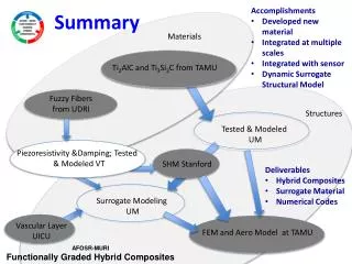
OAWL IDL Subsystems Integrated Lidar Transmitter Integrated Lidar Receiver Payload Controller Payload (incl. JEM-EF Interface) Ball Aerospace & Technologies Corp. and NASA Earth Science & Technology Office OAWL 2012 Instrument Design Lab (IDL) Study Results - Presented at the Working Group on Space-based Wind Lidar, 17 October 2012
Telescope for OAWL ISS Mission • Two look angles (two telescopes) • Elevation of 40 degrees off nadir • Azimuth angles of 45 degrees from the Ram and Wake directions • 70 cm diameter • Secondary mirror optic and structure obscurations are acceptable since this is not coherent detection. • Wavefront quality requirement: ~1-lambda at 632. • Telescope mirrors have 98% reflectivity at 355 nm (per IDL) • Weight < 11kg each. • Use scaled down version of the light-weighted Axsys telescopes in use on CALIPSO and MOLA (also GLAS, CATS-ISS, ATLAS). Ball Aerospace & Technologies Corp. and NASA Earth Science & Technology Office OAWL 2012 Instrument Design Lab (IDL) Study Results - Presented at the Working Group on Space-based Wind Lidar, 17 October 2012
OAWL baseline interferometer design • Smaller OPD version of the OAWL IIP system (TRL5) • OAWL Patents: US7929215(B1) and US8077294(B1). Ball Aerospace & Technologies Corp. and NASA Earth Science & Technology Office OAWL 2012 Instrument Design Lab (IDL) Study Results - Presented at the Working Group on Space-based Wind Lidar, 17 October 2012
Detectors & Data acquisition • Hamamatsu R7600U-200 PMTs (TRL5) – Quantity 4 • 43% Quantum Efficiency with Ultra-Bialkali • Low dark count & dark current, operate in analog mode • Will have heritage in the ATLAS PMTS R7600U-300. • Thermal cycling and radiation effects are not an issue (IDL statement). • Detection bandwidth: ~2 MHz • OAWL velocity range is NOT limited by detection bandwidth. Reducing detection bandwidth improves SNR – but decreases sample range resolution. • Processing & Control: Single Board Computer and FPGA (data acquisition & real-time processing) • Processed and averaged raw data transmitted and/or stored if needed. • All data rates verified to be feasible by IDL Ball Aerospace & Technologies Corp. and NASA Earth Science & Technology Office OAWL 2012 Instrument Design Lab (IDL) Study Results - Presented at the Working Group on Space-based Wind Lidar, 17 October 2012
Input to IDL: Ball OAWL JEM-EF design • Various components reused from CALIPSO (including PMT box designs, etalons, telescope, optical mounts, etc). • Input a baseline design concept shown at right (and next slide) • Pointing is 35 off nadir, allowing the system to be put in anyJEM-EF module. 40 achieved with IDL version. (restricts to modules 1 and 2) • Uses two 0.7m diameter Axsystelescopes (from CALIPSO and previous proposal models) Ball Aerospace & Technologies Corp. and NASA Earth Science & Technology Office OAWL 2012 Instrument Design Lab (IDL) Study Results - Presented at the Working Group on Space-based Wind Lidar, 17 October 2012
Ball OAWL concept design • There is actually a connector in the JEM-EF module here so a re-design was required – using the baseline concept as a starting point • IDL Mechanical engineers re-arranged the layout/components and redesigned the bench to come up with the design described on the following slides. Ball Aerospace & Technologies Corp. and NASA Earth Science & Technology Office OAWL 2012 Instrument Design Lab (IDL) Study Results - Presented at the Working Group on Space-based Wind Lidar, 17 October 2012
Overall View and Dimensions 1855 800 1000 Dims in mm are for the JEM-EF module
Conclusions, Cost Analysis, & Next Steps Ball Aerospace & Technologies Corp. and NASA Earth Science & Technology Office OAWL 2012 Instrument Design Lab (IDL) Study Results - Presented at the Working Group on Space-based Wind Lidar, 17 October 2012
OAWL IDL Study - Output Summaries • Laser: “TRL5 can be reached quickly by simply building a final form, fit, and function unit at Fibertek. Then pursuit of TRL6 can begin with Flight Qual.” • Electrical: “No electrical tall poles or low TRL concerns.” “The OAWL Raw Data rate is well below the 100Mbps bandwidth of the ISS HRDL and poses no concern.” • Flight Software: “Line Of Code estimation shows 79% code reuse for MEB. High heritage based on Ball/GSFC approach. …No technical show-stoppers” • Mechanical: “It fits! Re-packaged the optics and telescopes to fit within the JEM attached payload envelope.” • Optical: “Beryllium telescopes have a lot of flight heritage for this spaceflight application and should be considered high TRL. 355 nm operating wavelength poses minimal risk to design due to proven Ni plating technology and HR coatings. • Detectors: “PMTs have flown on many space flight missions including the Compton gamma ray telescope…Thermal cycling and radiation effects are not an issue…TRL of these PMTs is TRL-5” • Reliability: “Instrument exceeds 80% Reliability at 1 year operation with lower confidence limit in excess of 70%. Degraded Science (one laser) Reliability exceeds 95% at 1 year operation.” Conclusion: The OAWL IDL Baseline design is feasible and fits within the power, volume, mass, and thermal budgets of the ISS JEM-EF module. Ball Aerospace & Technologies Corp. and NASA Earth Science & Technology Office OAWL 2012 Instrument Design Lab (IDL) Study Results - Presented at the Working Group on Space-based Wind Lidar, 17 October 2012
Cost Summary & Analysis • Costing done based on 5-year mission (EV-4 type schedule) • Costed as an unmanned mission, Class B Electronics. • Total IDL Cost Estimate for OAWLon the ISS: < $100M. This includes • Instrument (PRICE-H costed) including 5% misc. hardware and Integration & Test • software (SEER-SEM costed) & software simulator • extras (testing, flight spares, GSE etc.) • This is in-scope with Ball Cost Estimates for similar systems. • Cost Variations • IDL Laser costs were high (>2X) compared to Fibertek ROM • IDL telescope costs were ~2X higher than Axsys ROM. • Some “manned mission” type requirements may add cost, but it was not specified where/how they would apply. • No adjustments were made for a Class D mission or for ISS capabilities (i.e. to handle large masses, etc. - these are not “knobs” in their Price-H model) Ball Aerospace & Technologies Corp. and NASA Earth Science & Technology Office OAWL 2012 Instrument Design Lab (IDL) Study Results - Presented at the Working Group on Space-based Wind Lidar, 17 October 2012
IDL Lessons • The IDL is an important step/gate for any instrument concept and the extra “eyes” on the system designs, and suggestions for alternative components are quite valuable. • The IDL may be best suited for systems in the earlier stages of design: Some of the extra Ball effort to help OAWL “catch-up” to the hybrid system IDL concept(s) was offset by the IDL process for an instruments’ “first time in.” • Difficult to balance Ball Proprietary issues with need to share Ball designs with the Goddard IDL employees who may also work on competitive instruments. • Costing information provided to Ball was incomplete due to “Goddard proprietary” algorithms. • Uncertainties (in subsystem designs and/or gaps in the knowledge base of the IDL team) lead to higher costs. Less experience on the IDL team with lidars, ISS system designs, and ISS costing likely lead to an overestimation of cost. • Coming in with a mature design and experienced team help lead to a more realistic cost for OAWL. The Ball OAWL team has a great deal of combined experience that includes building and flying CALIPSO, building & demonstrating OAWL hardware, designing and performing trades for other lidars on the ISS, lidar radiometric modeling, space-flight hardware, etc. Ball Aerospace & Technologies Corp. and NASA Earth Science & Technology Office OAWL 2012 Instrument Design Lab (IDL) Study Results - Presented at the Working Group on Space-based Wind Lidar, 17 October 2012
Next Steps • Where to focus the TRL development to reduce cost? • Lifetime laser at 355 nm (to raise laser TRL to 6, according to Goddard laser-TRL definitions): Would benefit OAWL, TWiLiTE, FIDDL, and others • PMT Detector space-qualification • Space-qualified FPGA board design and data processing algorithm development • Space-qualified thermal management systems for ISS-based laser systems • OAWL EDU build and aircraft flight testing • Adding the Molecular Channel - Double Edge Etalon • FIDDL (Fabry-perot for the Integrated Direct Detection Lidar) is currently under development at Ball to show the full atmospheric winds at 355 nm approach. • Laser, telescope, power, data acquisition, cooling, etc. – all apply. Need to add the Molecular Receiver: etalon and controller, detectors, entrance/exit optics, etc. Goal: One system, one laser, global winds & aerosols. Ball Aerospace & Technologies Corp. and NASA Earth Science & Technology Office OAWL 2012 Instrument Design Lab (IDL) Study Results - Presented at the Working Group on Space-based Wind Lidar, 17 October 2012
OAWL Presentations & Publications Wind Lidar Working Group Presentations • Jan 2009 (Destin, FL)- OAWL Progress and Plans: Grund, Pierce, Howell, Ostaszewski • Jun 2009 (Wintergreen, VA) -OAWL System Development Status : Grund, Pierce, Howell, Ostaszewski • Feb 2010 (Destin, FL) - OAWL IIP Development Status: Year 1.5: Grund, Howell, Ostaszewski, Pierce, Tucker • Aug 2010 (Bar Harbor, ME) – OAWL IIP Development Status: Year 2.0: Grund, Tucker, Howell, Ostaszewski, Pierce. • Feb 2011 (Coconut Grove, FL)- First Optical Autocovariance Wind Lidar Measurements and Status of the OAWL IIP: Grund and Tucker. • Aug 2011 (Boulder, CO) – Results from the OAWL IIP Ground Validation: Tucker, T. Delker, and C. Grund. • May 2012 (Miami, FL) - Successes of the OAWL IIP and next steps (with a FIDDL): S. Tucker, T. Delker, C. Weimer. • ESTO ESTF: • 6/2010 Development and Demonstration of an Optical Autocovariance Direct Detection Wind Lidar: Grund, Tucker, Pierce, Ostasziewski, Kanizay, Demara, Howell, ESTF2010 • 6/2011 - First Demonstration of an Optical Autocovariance Direct Detection Doppler Wind Lidar (OAWL): Grund, Tucker, and Delker, ESTF2011. Publications • 2009 - SPIE Defense and Security Sensors Symposium, paper and talk: “Optical Autocovariance Direct Detection Lidar for Simultaneous Wind, Aerosol, and Chemistry Profiling from Ground, Air, and Space Platforms”, Grund, Howell, Pierce, and Stephens • Jan 2011 - “Optical Autocovariance Wind Lidar (OAWL): A New Approach to Direct-Detection Doppler Wind Profiling “,Christian J. Grund, and Sara C. Tucker , talk and extended abstract: 5th Symposium on Lidar Atmospheric Applications, AMS Annual Meeting, Seattle, WA. Presentations & Posters • 2008 - AGU fall meeting in December. Poster: “Enabling Characteristics of Optical Autocovariance Lidar for Global Wind and Aerosol Profiling”, Grund, Stephens, Lieber, and Weimer • 2009 - SPIE Defense and Security Sensors Symposium, paper and talk: “Optical Autocovariance Direct Detection Lidar for Simultaneous Wind, Aerosol, and Chemistry Profiling from Ground, Air, and Space Platforms”, Grund, Howell, Pierce, and Stephens • Jan 2011 - “Optical Autocovariance Wind Lidar (OAWL): A New Approach to Direct-Detection Doppler Wind Profiling “,Christian J. Grund, and Sara C. Tucker , talk and extended abstract: 5th Symposium on Lidar Atmospheric Applications, AMS Annual Meeting, Seattle, WA. • Jan 2012 – “Wind Profiling with the Optical Autocovariance Wind Lidar: Results of Validation Testing,” AND “Optical Autocovariance Wind Lidar for Atmospheric Research,” S. Tucker, C. Grund, T. Delker, M. Adkins, B. Good, P. Kaptchen, and D. Gleeson, 2012 AMS Annual Meeting, New Orleans, LA. Ball Aerospace & Technologies Corp. and NASA Earth Science & Technology Office OAWL 2012 Instrument Design Lab (IDL) Study Results - Presented at the Working Group on Space-based Wind Lidar, 17 October 2012