Electronics Orientation
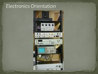
Electronics Orientation. ‘Rig’ components Audio Amplifier/Speaker Stimulator DC Strain Gauge Amplifier AC Amplifier AM Amplifier Analog Oscilloscope Power Supply. Faraday Cage & plate. Metal plate is on tennis balls for vibration isolation. Cables/Connections Banana plugs

Electronics Orientation
E N D
Presentation Transcript
‘Rig’ components Audio Amplifier/Speaker Stimulator DC Strain Gauge Amplifier AC Amplifier AM Amplifier Analog Oscilloscope Power Supply
Faraday Cage & plate Metal plate is on tennis balls for vibration isolation .
Cables/Connections Banana plugs BNC cables Alligator Clips Adapters BNC-to-Alligator BNC-to-Banana (male/female) Combinations (male/female) Splitters BNC – ‘T’ Head Stage AC Head Stage (male-female) DC Head Stage (female-female) Strain Gauge
Electronics Orientation Exercise • Other Equipment Pipette Pullers Stroboscope
Signal Analysis System Setup Adapters: 2 T’s, 3 BNC’S Plug in equipment Signal generator to oscilloscope Ch 2 Adapters: alligator-to-BNC Connect to oscilloscope channel 2 Head Stage connected to AC amplifier Connect AC Amp output (via T and BNC) to three data analysis devices To audio amp A/V adapter on rear To 0scilloscope (channel 1) To PC: connect to Ch 0 on rack (upper left) Work through part one of the electronics orientation handout
VI input Audio Stimulator AC Amp DC AMP AM Systems AMP Oscilloscope Power supply Using alligators, ground plate to cage and cage to rack G1 G2 Com Input Output Stimulus Generator Headstage (input)
Make sure signal generator is off, remove connection from oscilloscope Connect to signal generator to AC headstage Alligator to G1 and G2, not COM Before turning on signal generator, check level of amplification- set amplifier to lowest amplification. Work through part two of the equipment testing handout PLEASE HAVE SOMEONE CHECK YOUR SETTINGS BEFORE TURNING ON AMPLIFIER
VI input Audio Stimulator AC Amp DC AMP AM Systems AMP Oscilloscope Power supply Stimulus Generator Using alligators, ground plate to cage and cage to rack G1 G2 Com Input Output Headstage (input)
Electronics Problem solving • Get your electronics set before getting the specimin • Is it plugged in? • Is it turned on? • Check connections • Check grounds (plate to cage, cage to rack) • Is your amplification correct? Check settings in handout • Is your scaling (time base and gain/voltage) correct? • You can check the connections and settings on the demo rig or on a classmate’s rig.