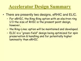
Super KEKB Accelerator Upgrade Plan Summary
Detailed upgrade plans for Super KEKB accelerator including RF system improvements, beam stability, collision considerations, and future upgrade scenarios. Analysis of beam physics, magnets design, and injector linac for enhanced performance.

Super KEKB Accelerator Upgrade Plan Summary
E N D
Presentation Transcript
Accelerator Summary 1/22/2004 K. Oide (KEK)
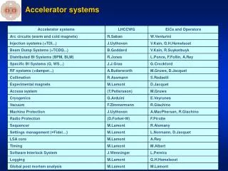
Accelerator Session:PEP-II IR Upgrade M. Sullivan (SLAC)Super KEKB Optics & IR Y. Ohnishi(KEK)Super-PEP-II IR Upgrade M. Sullivan (SLAC)HOM calculations of new RF cavities A. Novokhatski (SLAC)RF system for Super-KEKB K. Akai (KEK)RF and longitudinal stability in Super-PEPII D. Teytelman (SLAC)Accelerator Discussion and Contingency:Coherent Synch. Rad. Y. Ohnishi(KEK)Luminosity of Super KEKB J. Flanagan(KEK)
Higher Current: • More rf power, cooling, injector, … • More HOM heating (more bunches) • Beam Instabilities • Electron clouds, fast ions, … • Head-on collision: • Parasitic crossing for large number of bunches • Background due to separation bends • Crossing angle: • degrades xy, < 0.06 • restored by crab crossing • Smaller by*: • Smaller physical/dynamic aperture • Shorter lifetime, more background, … • Shorter sz: • More HOM heating • Coherent synch. rad. • Shorter lifetime, more background
PEP-II Proposed Upgrade Plans • Now Projected Upgrade • LER energy 3.1 3.1 3.1 GeV • HER energy 9.0 9.0 9.0 GeV • LER current 1.8 3.6 4.5 A • HER current 1.0 1.8 2.0 A • y*12.58.56 mm • x* 28 28 28 cm • X emittance 50 40 40 nm-rad • Estimated sy* 4.9 3.6 2.7 mm • Bunch spacing 1.89 1.26 1.26 m • Number of bunches 1034 1500 1700 • Collision angle head-on head-on head-on mrads • Beam pipe radius 2.5 2.5 2.5 cm • Luminosity 6.61033 1.81034 3.31034cm-2 sec-1 M. Sullivan-1
The tune shift from the first parasitic crossing normalized to the main collision tune shift as a function of crossing angle and plotted for various by* values for PEP-II (courtesy of Marica Biagini) LER PC tune shifts vs q/2 for different by* normalized to the IP tune shift for sl (bunch length) = 9 and 7 mm M. Sullivan-1 HER PC tune shifts vs q/2 for different by* normalized to the IP tune shift for sl = 9 and 7 mm
Summary M. Sullivan-1 • The initial upgrade proposal replaced the last 4 slices of the B1 magnets with quadrupole field. This allows for lower beta y* values with a smaller increase in the maximum beta y. • The replacement of the B1 slices with quad field introduces a ± 3.3 mrad crossing angle at the IP which reduces the beam-beam effect at the 1st parasitic crossing. However, recent beam-beam simulations indicate a luminosity reduction for beams with a crossing angle. • An alternative proposal currently under study is to strengthen the IP end of QD1 effectively moving the center of the magnet closer to the IP. At the same time, increase the beam separation at the 1st parasitic crossing by increasing the strength of the initial B1 slices. This maintains the PEP-II head-on collision. • The high beam currents of the upgrade plans generate significant SR power in the IR that must be handled • SR backgrounds look like they can be controlled but have not yet been thoroughly studied
Y. Ohnishi Super KEKB IR magnet layout x (m) QC2RE QC2LP QC1RE ← LER QCSL QCSR QC1LE QC2RP HER → QC2LE s (m) IP
Y. Ohnishi QCS for SuperKEKB and KEKB q=17° q=150° SuperKEKB KEKB EFC Move QCS closer to IP and compensation solenoid is divided into two parts, one is overlaid with QCS.
QC1(superconducting magnet) QC1RE QC1LE Leakage field<1.5 Gauss Leakage field<20 Gauss G=34 T/m Leff=0.266 m Iop=1319 A, Bmax=3.28 T Iop/Ic=73% G=42.86 T/m Leff=0.232 m Iop=1319A, Bmax=1.62 T Iop/Ic=59% Y. Ohnishi
Y. Ohnishi Injector linac for SuperKEKB Positron dumping ring (1 GeV) Positron energy upgrade with C-band for energy exchange (e- LER / e+ HER)
Y. Ohnishi Dynamic aperture • Dynamic aperture in LER • Machine errors are not • included. • Transverse aperture is • acceptable. Injection beam
Y. Ohnishi Summary • Strategy of IR design • Positron DR prior to IR upgrade • Design of IR magnets • Two options for QC1 : • superconducting / normal • IR magnets is designed so that SR from QCS does not hit QC1 and QC2 as possible. • Vacuum chamber in IR is under study. • Optics for SuperKEKB is designed. • Dynamic aperture in LER ( Dp/p0 ~ 1.5 %) • Injection aperture can be kept.
PEP-III Super B • Now Projected Upgrade Super B • LER energy 3.1 3.1 3.1? 3.5 GeV • HER energy 9.0 9.0 9.0? 8.0 GeV • LER current 1.8 3.6 4.5 22.2 A • HER current 1.0 1.8 2.0 9.7 A • y*12.58.56.51.5 mm • x* 28 28 28 15 cm • X emittance 50 40 40 70 nm-rad • Estimated sy* 4.9 3.6 2.7 1.7 mm • Bunch spacing 1.89 ~1.5 1.26 0.63 m • Number of bunches 1034 1500 1700 3400 • Collision angle head-on head-on 03.2512-14 mrads • Beam pipe radius 2.5 2.5 2.5 1.5-2.0? cm • Luminosity 6.61033 1.81034 3.3103411036 cm-2 sec-1 M. Sullivan-2
A 1 cm radius beam pipe might be possible now M. Sullivan-2
Summary M. Sullivan-2 A super B-factory IR is quite challenging The very high beam currents rule out designs in which SR fans are intercepted locally The IR design in the areas of detector backgrounds, HOM power and SR quadrupole radiation are all very difficult and need to be thoroughly studied. The trick is to find a solution that satisfies all of these requirements without compromising the physics
Electric force lines of wake field excited by a short bunch in PEP-II cavity A. Novokhatski
Spectrum of 952 MHz cavity Loss impedance of this cavity is 3.4 times smaller than impedance of PEP-II cavity for a bunch of 1.8mm length. R/Q of the cavity is 66 Ohms A. Novokhatski
Optimization of the cavity shape Gives better R/Q =78 Ohm and less loss impedance by 8% A. Novokhatski
Minimum loss impedance and loss impedances of different cavities A. Novokhatski
Summary A. Novokhatski • To be continued!
RF parameters for SuperKEKB K. Akai
Modification of LER-ARES • The ARES in LER will be remodeled to increase the stored energy further. • By enlarging the coupling hole between the A-C cavities, Us/Ua will be increased from 9 to 15. • Storage cavity is reused. Coupling impedance for the p/2 mode T. Kageyama, et. al. Growth rate as a function of Us/Ua K. Akai
Improve the ARES-HOM dampers K. Akai • The waveguide dampers • High power tested up to 3.3 kW/bullet (26 kW/cavity). • Upgrade needed to 80 kW/cavity. • Will be tested at higher power with a new high power source. • The number of bullets/waveguide will be increased. • The grooved beam pipe dampers • High power tested up to 0.5 kW/groove (2 kW/cavity). • Upgrade needed to 20 kW/cavity. • A new type of damper? Such as a winged chamber with SiC bullets? Y. Suetsugu, et. al.
SCC HOM power and beam pipe K. Akai • Present HOM dampers in KEKB have been operated up to 12 kW/cavity.
Schematic drawing of new crab cavity K. Akai • (Left) The cross-shaped waveguide dampers and coaxial dampers are attached at the squashed-cell. • (Right) Cross section of the coaxial damper at the cut plane of Y-Y’.
Summary of SuperKEKB RF system K. Akai • Base plan: • The existing RF system will be used as much as possible, with improvements as necessary. • The ARES (LER, HER) and SCC (HER) will be used. • CBI due to the accelerating mode • LER-ARES will be modified, that eases the growth time from 0.3ms to 1.6ms. • The -1 mode damper will suppress the CBI with a growth time of 1 ms. • HOM dampers • Performance limit of the present HOM dampers will be tested. • A new HOM damper may by necessary, particularly for the GBP damper. • Large RF power • Improvement of the couplers will continue to double the operating power. • The number of RF unit will be doubled. • Crab cavity • A new crab cavity is proposed, which can be used at 10 A. • The design is completed. It has sufficient property for SuperKEKB.
Y.Ohnishi Coherent Synchrotron Radiation Energy change / particle v.s z/sz KEKB LER/ 2.6A (5120) Acceleration Numerical simulation with mesh (Ago and Yokoya, to be published or details found in LoI) DE ≈ 100 kV/turn (5 V/pC) for 9.4 A, LER Deceleration Stubility must be checked