1 / 40

GEOMETRIC DIMENSIONING AND TOLERANCING (GD&T)

GEOMETRIC DIMENSIONING AND TOLERANCING (GD&T) Purpose is to describe the engineering intent of parts and assemblies Uses symbols to specify geometric characteristics and dimensional requirements Current GD&T standard: ANSI/ASME Y14.5M-2009 Symbols for:

twyla
Télécharger la présentation

GEOMETRIC DIMENSIONING AND TOLERANCING (GD&T)

An Image/Link below is provided (as is) to download presentation Download Policy: Content on the Website is provided to you AS IS for your information and personal use and may not be sold / licensed / shared on other websites without getting consent from its author. Content is provided to you AS IS for your information and personal use only. Download presentation by click this link. While downloading, if for some reason you are not able to download a presentation, the publisher may have deleted the file from their server. During download, if you can't get a presentation, the file might be deleted by the publisher.

E N D

Presentation Transcript


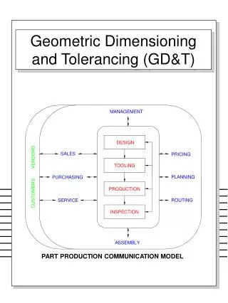
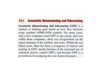
  1. GEOMETRIC DIMENSIONING AND TOLERANCING (GD&T) • Purpose is to describe the engineering intent of parts and assemblies • Uses symbols to specify geometric characteristics and dimensional requirements • Current GD&T standard: ANSI/ASME Y14.5M-2009 • Symbols for: • Form and profile tolerances, orientation tolerances, location tolerances, runout tolerances

  2. GEOMETRIC DIMENSIONING AND TOLERANCING (GD&T)

  3. GEOMETRIC DIMENSIONING AND TOLERANCING (GD&T) • Feature control frame

  4. GEOMETRIC DIMENSIONING AND TOLERANCING (GD&T)

  5. GEOMETRIC DIMENSIONING AND TOLERANCING (GD&T) • Examples of Modifiers • MMC – Maximum Material Condition • LMC – Least Material Condition

  6. GEOMETRIC DIMENSIONING AND TOLERANCING (GD&T)

  7. GEOMETRIC DIMENSIONING AND TOLERANCING (GD&T)

  8. GEOMETRIC DIMENSIONING AND TOLERANCING (GD&T) • ISO standard of preferred metric limits and fits: In the dimension 16h11, the tolerance zone is specified by a letter and a number, I.e. h11. An uppercase letter indicates that the tolerance applies to the hole; a lowercase letter indicates the tolerance applies to the shaft.

  9. GEOMETRIC DIMENSIONING AND TOLERANCING (GD&T)

  10. GEOMETRIC DIMENSIONING AND TOLERANCING (GD&T)

  11. GEOMETRIC DIMENSIONING AND TOLERANCING (GD&T)

  12. GEOMETRIC DIMENSIONING AND TOLERANCING (GD&T)

  13. GEOMETRIC DIMENSIONING AND TOLERANCING (GD&T)

  14. GEOMETRIC DIMENSIONING AND TOLERANCING (GD&T)

  15. GEOMETRIC DIMENSIONING AND TOLERANCING (GD&T)

  16. GEOMETRIC DIMENSIONING AND TOLERANCING (GD&T)

  17. GEOMETRIC DIMENSIONING AND TOLERANCING (GD&T)

  18. GEOMETRIC DIMENSIONING AND TOLERANCING (GD&T)

  19. GD&T

  20. GD&T

  21. GD&T • Basic Dimension: Theoretically exact, untoleranced dimensions that specify the perfect location, size, shape, or angle of a feature. • Basic dimensions are identified by enclosing the dimension in a box. • Basic dimensions specify theoretically exact value from which variations are defined through feature control frames as well as toleranced features and notes. • General tolerances do not apply to basic dimensions.

  22. GD&T

  23. GD&T – Datum Surfaces and Features

  24. GD&T – Datum Surfaces and Features

  25. GEOMETRIC DIMENSIONING AND TOLERANCING (GD&T)

  26. GD&T – Datum Surfaces and Features

  27. GD&T – Datum Surfaces and Features

  28. GD&T – Datum Surfaces and Features

  29. GD&T – Datum Surfaces and Features

  30. GD&T – Datum Surfaces and Features

  31. GD&T – Datum Surfaces and Features

  32. GD&T – Datum Surfaces and Features

  33. GD&T – Datum Surfaces and Features

  34. GD&T – Datum Surfaces and Features

  35. GD&T – Datum Surfaces and Features

  36. GD&T – Datum Surfaces and Features

  37. GD&T – Datum Surfaces and Features

More Related