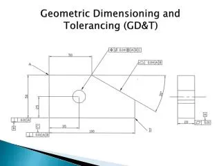
Geometric Dimensioning and Tolerancing
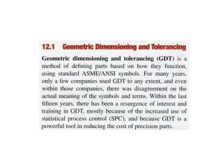
Geometric Dimensioning and Tolerancing. FORM TOLERANCES. LOCATION TOLERANCE . A. GDT PROBLEMS . Are all of these auto parts made in the same factory by the same company?. What is the purpose of GDT?. It is used on mating parts in order to assure that they are ‘interchangeable’.


Geometric Dimensioning and Tolerancing
E N D
Presentation Transcript
FORM TOLERANCES LOCATION TOLERANCE A GDT PROBLEMS
Are all of these auto parts made in the same factory by the same company?
What is the purpose of GDT? It is used on mating parts in order to assure that they are ‘interchangeable’.
Where did GDT come from? THE AMERICANSOCIETY OF MECHANICALENGINEERS (ASME) CREATED A GLOBAL STANDARD TITLED ASME Y14.5-2009FOR DIMENSIONING AND TOLERANCING.
What does this sign mean? SPEED LIMIT 65 40 MINIMUM
What are the LIMITS? Any speed in between the limits is within the acceptable range or zone. SPEED LIMIT 65 40 MINIMUM UPPER LIMIT MAX. MIN. LOWER LIMIT What happens if you go out of that zone?
What is the TOLERANCE? The difference between the upper and lower limit equals the Tolerancezone. 65 UPPER LIMIT -40 LOWER LIMIT 25 = TOLERANCE ZONE SPEED LIMIT 65 40 MINIMUM 25 Tolerance =is the total amount that a dimension is permitted to vary.
What are the LIMITS? SPECIFIED DIMENSION 12.75 12.25 12.50 + 0.25 TOLERANCE LIMITS
MMC & LMCMAXIMUM MATERIAL CONDITIONAND LEAST MATERIAL CONDITION
What is the difference between these two glazed doughnuts? Both of these doughnuts cost 90 cents. Which one is the best buy? Why? Which one was made with the most or maximum amount of dough? M L MMC = Maximum Material Condition LMC = Least Material Condition
MAXIMUM MATERIAL CONDITION (MMC) = • IS WHERE A FEATURE CONTAINS THE MAXIMUM AMOUNT OF MATERIAL PERMITTED WITHIN THE STATED LIMITS. • (SEE BOOK EXAMPLE 1-8 & 1-9) 1.75 1.73 n Look at the limits of the O.D. and the I.D. of the washer. Which ones represent the washer at MMC? M 0.75 0.73 n
MAXIMUM MATERIAL CONDITION (MMC) = • IS WHERE A FEATURE CONTAINS THE MAXIMUM AMOUNT OF MATERIAL PERMITTED WITHIN THE STATED LIMITS. • (SEE BOOK EXAMPLE 1-8 & 1-9) MMC OF THE O.D. 1.75 1.73 n M 0.75 0.73 n MMC OF THE I.D.
LEAST MATERIAL CONDITION (LMC) = • IS WHERE A FEATURE CONTAINS THE LEAST AMOUNT OF • MATERIAL PERMITTED WITHIN THE STATED LIMITS. • (SEE EXAMPLE 1-10, 1-11) 1.75 1.73 n Look at the limits of the O.D. and the I.D. of the washer. Which ones represent the washer at LMC? L 0.75 0.73 n
LEAST MATERIAL CONDITION (LMC) = • IS WHERE A FEATURE CONTAINS THE LEAST AMOUNT OF • MATERIAL PERMITTED WITHIN THE STATED LIMITS. • (SEE EXAMPLE 1-10, 1-11) 1.75 1.73 n LMC OF THE O.D. L 0.75 0.73 LMC OF THE I.D. n
MAXIMUM MATERIAL CONDITION (MMC) = • IS WHERE A FEATURE CONTAINS THE MAXIMUM AMOUNT OF MATERIAL PERMITTED WITHIN THE STATED LIMITS. • (SEE BOOK EXAMPLE 1-8 & 1-9) MMC OF THE O.D. 1.75 1.73 n M 0.75 0.73 n MMC OF THE I.D.
RFS Sometimes a geometric tolerance will be applied to a dimension at its MMC or it LMC. However……….. • REGARDLESS OF FEATURE SIZE (RFS) =IS THE TERM USED WHEN A GEOMETRIC TOLERANCE OR DATUM APPLIES AT ANY INCREMENT OF SIZE WITHIN ITS UPPER OR LOWER LIMIT.(SEE EXAMPLE 4-7)
Review 1. What does ASME Y14.5-2009 stand for? IT IS A GLOBAL STANDARD FOR DIMENSIONING AND TOLERANCING. 2. What is tolerance? IT IS THE TOTAL AMOUNT THAT A DIMENSION IS PERMITTED TO VARY. 3. What are limits? ARE THE LARGEST AND SMALLEST (THE MAXIMUM AND MINIMUM) NUMERICAL VALUE THAT A FEATURES DIMENSIONS CAN BE. 4. How do they differ? TOLERANCE IS THE DIFFERENCE BETWEEN A DIMENSIONS UPPER AND LOWER LIMITS. 5. What is meant by Maximum Material Condition? IS WHERE A FEATURE CONTAINS THE MAXIMUM AMOUNT OF MATERIAL PERMITTED WITHIN THE STATED LIMITS. 6. What is meant by Least Material Condition? IS WHERE A FEATURE CONTAINS THE LEAST AMOUNT OF MATERIAL PERMITTED WITHIN THE STATED LIMITS. 7. What is meant by RFS? REGARDLESS OF FEATURE SIZE
Feature Control Frame • A SYMBOL MADE UP OF COMPARTMENTS CONTAINING THE GEOMETRIC CHARACTERISTIC • SYMBOL AND THE TOLERANCE. (SEE PAGE 44, EXAMPLE 2-10)
DATUMS A
Locate the projector If we wanted to mount our projector from the ceiling what three dimensions would we need……. and in what order? A Screen Projector Plan View
Locate the projector B Screen Projector Plan View
Locate the projector Mounting Bracket C Screen A B C Projector Elevation View Floor
DATUMS A DATUMS=ARE PLANES, SURFACES, POINTS, LINES OR AXES FROM WHICH MEASUREMENTS ARE MADE. THEY IDENTIFY SURFACES OR AXES THAT ARE IMPORTANT TO THE FUNCTION OF THE DESIGN.
Datum Planes A A
Datum Planes B A A
C B A A
Datum Placement on Drawings C B A DATUM FEATURE SYMBOLS ARE PLACED ON THE EDGE VIEW OR ON EXTENSION LINES. A THE ORDER IN WHICH THE DATUM REFERENCE LETTERS ARE PLACED IN THE FEATURE CONTROL FRAME SIGNIFY THEIR IMPORTANCE. THIS IS CALLED THE ORDER OF PRECEDENCE.
Datum Axis Placement on Drawings .25 B A DATUM AXIS
Datum Axis Placement on Drawings ON THE LEADER LINE SHOULDER ON THE OUTSIDE SURFACE (THE EDGE) OF A CYLINDRICAL FEATURE. A THE SYMBOL CAN ALSO BE PLACED ON THE EXTENSION LINE.
Datum Axis Placement on Drawings THE DATUM SYMBOL CAN ALSO BE ATTACHED TO THE FEATURE CONTROL FRAME. A
Datum Target Placement on Drawings At times only a small area on a surface will be used as a datum. To identify these areas a Datum Target Symbol is used. 12 A X DATUM TARGET SYMBOL = ARE USED TO DESIGNATE POINTS OR A SPECIFIC SURFACE AREA. THEY ARE USED WHEN IT MAY NOT BE POSSIBLE TO ESTABLISH AN ENTIRE SURFACE AS A DATUM. (SEE EXAMPLE 3-12 PAGE 71)
12 X
Review 1. Define Datum? Are planes, surfaces, points, lines or axes from which measurements are made. They identify surfaces or axes that are important to the function of the design. 2. Describe the Datum Feature symbol? 3. List three areas where datum symbols should be placed? • Edge view • Extension lines • Leader line shoulder • Feature control frame A
Review (cont.) 4. When are Datum Target Symbols used? They are used to designate points or a specific surface area. They are used when it may not be possible to establish an entire surface as a datum. 5. Describe the Datum Target symbol?
L L M
What are Form Tolerances? • Form Tolerances are applied to single features and, therefore, are not related to a datum. • They specify a zone in which the dimensioned feature must be controlled.
Straightness a Form Tolerance A condition where an element of a surface or an axis is in a straight line.