Download
1 / 16
220 likes | 617 Vues
Geometric Dimensioning and Tolerancing. Chapter 5, General Rules. Review. Chap 1 – Introduction importance of interchangeable parts need to avoid ambiguity in drawings Chap 2 – Symbols & Abbreviations Dimensioning Symbols ; Geometric Characteristics ; Modifying Symbols Chap 3 – Datums

E N D
Geometric Dimensioning and Tolerancing Chapter 5, General Rules
Review • Chap 1 – Introduction • importance of interchangeable parts • need to avoid ambiguity in drawings • Chap 2 – Symbols & Abbreviations • Dimensioning Symbols ; Geometric Characteristics ; Modifying Symbols • Chap 3 – Datums • datums define coordinate systems from which measurements are taken during part inspection • Chap 4 – Feature Control Frames • defines a geometric characteristic of a feature or a relationship between different features
Overview of Rules • There are four general rules • Taylor’s rule. Limits of size. • Regardless of Feature Size (RFS) is the default. • Pitch cylinder axis is reference for thread and screws. • Virtual condition.
Rule 1 – Taylor’s Principle • Rule 1 states: • "where only a tolerance of size is specified, the limits of size of an individual feature prescribe the extent to which variations in its geometric form, as well as size, are allowed.“ • The feature surface may not exceed the limits of size. • When a feature is made atMMC, it must be of perfectform. • When not at MMC, the shapemay not extend beyond theMMC perfect form.
Rule 1 • Specification for a peg. • If made at MMC, .515, the peg must be perfectly straight.
Rule 1 • If made smaller than MMC, the peg can be bent or tapered. • However, it must not extend beyond the MMC perfect shape boundaries.
Limits of Size – Rule #1 Taylor Principle (1905) The limits of size “Rule #1” defines the size and form limits for regular, individual features. It requires perfect form at MMC and ensures the pin will fit in the hole. If the feature is made at MMC, its form must be perfect.
Limits of Size – Rule #1 The limits of size define the size, as well as the form of an individual feature. The form of the feature may vary within the size limits. If the feature is produced at its maximum material condition, the form must be perfect. The feature may be bent, tapered or out of round as it departs from the maximum material condition. (Envelope Principle, Taylor Principle)
Limits of Size – Rule #1 The limits of size define the size, as well as the form of an individual feature. The form of the feature may vary within the size limits. If the feature is produced at its maximum material condition, the form must be perfect. The feature may be bent, tapered or out of round as it departs from the maximum material condition. (Envelope Principle, Taylor Principle Verification Check #1 (form or shape check)
Limits of Size – Rule #1 The limits of size define the size, as well as the form of an individual feature. The form of the feature may vary within the size limits. If the feature is produced at its maximum material condition, the form must be perfect. The feature may be bent, tapered or out of round as it departs from the maximum material condition. (Envelope Principle, Taylor Principle Verification Check #2 (local size check)
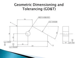
Limits of Size – Rule #1 . 8 7 4 . 8 7 0 M e a n s t h i s . 8 7 0 M i n . 8 7 0 M i n . 8 7 4 M a x . 8 7 4 M a x Can be tapered within .004 Form can be refined with cylindricity. Can be waisted within .004. Form can be refined with straightness or cylindricity. . 8 7 0 M i n . 8 7 0 M i n . 8 7 4 M a x . 8 7 4 M a x Can be barreled within .004 Form can be refined with straightness or cylindricity. Can be bent within .004. Form can be refined with straightness or cylindricity. . 8 7 4 M a x . 8 7 4 M a x . 8 7 0 M i n . 8 7 0 M i n Can be oval or out of round within .004 Form can be refined with circularity or cylindricity. Can be “D” shaped out of round within .004 Form can be refined with circularity or cylindricity. T h i s o n t h e d r a w i n g
Rule 1 • Designers may wish to permit a feature to vary beyond the boundary of perfect form at MMC. • In this case, the symbol is used after the dimension to indicate independency. • Also, rule 1 does not control any interrelation of features. The outer and inner surfaces each obey rule 1 individually.
Rule 2 – RFS default • Regardless of Feature Size (RFS) applies, with respect to the individual tolerance, datum reference, or both, where no modifying symbol is specified. • This will be discussed further with regards to MMC and LMC modifiers.
Rule 3 - threads • Rule Three applies to all screw threads, gears, and splines. • "for each tolerance of orientation or position and datum reference specified for screw threads applies to the axis of the thread derived from the pitch cylinder, for gears and splines, the MAJOR DIA., PITCH DIA., or MINOR DIA. must be specified."
Rule 4 – datum/virtual condition rule • applies to datum features subject to size variation • "depending on whether it is used as a primary, secondary, or tertiary datum, a virtual condition exists for a datum feature of size where its axis or center line is controlled by a geometric tolerance.“ • virtual condition is the worst acceptable condition of a feature • the virtual condition for an internal or external feature is the LMC size
Evaluation size form individual MMC LMC MMC zero RFS pitch beneath foundation not