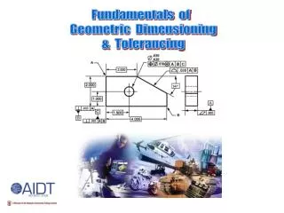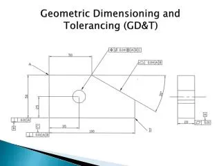
Geometric Dimensioning and Tolerancing
Geometric Dimensioning and Tolerancing. Chapter 4 , Feature Control Frames. Review. Chap 1 – Introduction importance of interchangeable parts need to avoid ambiguity in drawings Chap 2 – Symbols & Abbreviations Dimensioning Symbols ; Geometric Characteristics ; Modifying Symbols


Geometric Dimensioning and Tolerancing
E N D
Presentation Transcript
Geometric Dimensioning and Tolerancing Chapter 4, Feature Control Frames
Review • Chap 1 – Introduction • importance of interchangeable parts • need to avoid ambiguity in drawings • Chap 2 – Symbols & Abbreviations • Dimensioning Symbols ; Geometric Characteristics ; Modifying Symbols • Chap 3 – Datums • datums define coordinate systems from which measurements are taken during part inspection
Introduction • The feature control frame provides a specified control for single or multiple features. • A feature control frame must contain at least a geometric characteristic symbol and a tolerance value.
Geometric Characteristics Explained in detail in Chapters 6 and 8.
Attachment • The placement of the feature control frame governs what information it is conveying surface of cylindrical feature center axis of cylindrical feature
Attachment • 4 placement styles • The feature control frame is placed below a dimension pertaining to a feature. The leader is from the dimension. • A leader from the feature control frame runs to the controlled feature. • A side or end of the feature control frame is attached to an extension line from the feature. The feature surface must be a plane. • A side or end of the feature control frame is attached to a feature-of-size dimension extension line.
Content of a Feature Control Frame • The first compartment is always a geometric characteristic symbol. • The next compartment is a tolerance.
Content of a Feature Control Frame • The next compartments identify datums as needed to define the reference coordinate system. • The feature control frame may contain modifiers.
Types of Feature Control Frames • single • combined • feature given a tolerance and then identified as a datum
Evaluation control combined surface geometric characteristic tolerance left right primary line compartments no I O