Download
1 / 47
560 likes | 1.33k Vues
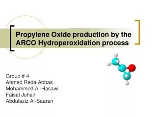
The Production of Propylene Oxide Using Cell Liquor. Meshal Al-Rumaidhi Hassan Ghanim Ali Al-Haddad Abdulrahman Habib Supervised by: Prof. : Mohammed Fahim Eng. : Yousif Ali. Agenda. Introduction Chlorohydrin Saponification and PO Recovery

E N D
The Production ofPropylene Oxide Using Cell Liquor Meshal Al-Rumaidhi Hassan Ghanim Ali Al-Haddad Abdulrahman Habib Supervised by: Prof. : Mohammed Fahim Eng. : Yousif Ali
Agenda • Introduction • Chlorohydrin • Saponification and PO Recovery • By‐Product Disposal Section • Problem Involved • The Principal Results • Conclusion
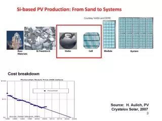
Introduction We estimated many factors and balances in the production of propylene oxide (PO) (50,659 Ib/hr) through propylene (C3H6), chlorine (Cl2) and water (H2O). These estimations will be simulated into HYSYS. Many data were collected from different resources to simplify the process .Our process consist of three sections: Chlorohydrin, Saponification and by-product disposal. We will describe each process briefly in the following slides.
Chlorohydrin Section
Chlorohydrin The first section is the chlorohydrin. we will describe the preparation of propylene chlorohydrin (PCH) which will converted to PO in the next section (Saponification section). Main: Sides:
Assumption •Reactor: conversion 97% , 40 psia, 60 oC. • Suitable fluid package used Wilson. • Propylene and propane are recycled back.
HYSYS Description The feed of chlorine and propylene is separated in fraction in (TEE‐100‐101); to produce specific value of PCH.
In reactors (CRV‐100‐103) the feed enters at 40 oC and 60 psia with an assumed overall conversion of 97%; there are three reactions involved, the main one produce propylene chlorohydrins (PCH) but the two sides reaction produce propylene dichloride (PDC) and di-chloro-di-iso-propyl-ether (DCIPE).Since the liquid phase from each reactor is hot (Because the reaction is exothermic) so it cooled by heat exchanger (E‐100‐102) to 40 oC.
The vapor phase are collected from above of each reactors in stream 4 (mainly H2O,HCl and un-reacted propane and propylene)
The vapor stream is treating with two splitters (X‐100-101) to separate water and PDC by using NaOH and DCIPE respectively. the propylene and propane un‐reacted are recycled (Raw material cost)(# iteration 3)
Saponification and PO Recovery We will describe the production of propylene oxide (PO); by using the propylene chlorohydrin (PCH) formed in (Chlorohydrin) section.
Assumptions •Since data was insufficient, we were compelled to assume the conversion rate of the reactors as 99.9%. Pressure of feed that enters the conversion reactor is 22 psia and temperature of 99 oC. Distillation Column
HYSYS Description We use conversion reactor and splitter instead of the try column because it consists of reaction and separator. The conversion reactor (99.9%) (CRV‐104), work at 99 oC 22 psia. there are two reaction involved, the main is to produced PO (Main product) and the other is to treat HCl acid produced in the first section. The vapor and liquid streams from the reactor are sending to splitter (X‐102) to separate undesired component such as: water and NaCl (Stream 15).
Waste Undesired component such as: water and NaCl (Stream 15)
The upper stream is cooled in (E‐104‐105) to make the liquid more; which will be the feed of distillation(T-100) and the vapor less; which will vented to atmosphere by using two phase separated (V‐100‐101); in first separator (V‐100) the liquid recycled(# iteration 3) to increased purity, but the vapor is sending to (V‐101).
There are three distillations columns in this section. First one (T-100) Used to separate PDC, DCIPE and Water from PO Assumption: (1) Reflux ratio 4, (Trays 22) . (2) Distillate rate 57,500 Ib/hr (Vapor) . (3) Recovery of PDC & DCIPE (0.999) and H2O (0.7) in liquid (LDIS 1). (4) Recovery of PO (0.99) in vapor (VDIS 1). (5) Press. drop 5 psia
Second distillation(T-101) used to separate PO from other component Assumption: (1) Reflux ratio 4, (Trays 22) . (2) Distillate rate 54,700 Ib/hr (Vapor) . (3) Recovery of other component (0.99) in liquid (LDIS 2). (4) Recovery of PO (0.999) in vapor (VDIS 2). (5) Press. drop 5 psia
Third distillation (T-102) used to achieved PO purity of 99.9% Assumption: (1) Reflux ratio 4, (Trays 10) . (2) Distillate rate 50,700 Ib/hr (Liquid) . (3) Recovery of other component (0.999) in vapor (Vent*). (4) Recovery of PO (1) in liquid (18). (5) Press. drop 5 psia
When the distillation process was complete, the exiting stream contained 50,659 Ib/hr of PO with purity of 99.9% (Near to what we have to get it 50,686 Ib/hr of PO with 99.9% purity) which mean the goal is achieved.
By‐Product Disposal Section We will describe the separation of propylene dichloride (PDC) and (DCIPE) dichlorodiisopropylether. We separate these two components because we could sale and market them.
HYSYS Description The liquid distilled (LDIS1) is send to tow phase separator (V‐103); which used as a temporary storage for shutdown cases. The liquid stream is splinted by (X‐103) to purify PDC and DCIPE. Then we prepare the stream to send it to the distillations by cooling it with heat exchanger (E‐107) and use two phase separator (V‐104).
The first distillation(T-103) used to separate PDC and DCIPE from the other components Assumption: (1) Reflux ratio 4, (Trays 30) . (2) Distillate rate 13200 Ib/hr (vapor) . (3) Recovery of Water (0.8) in vapor (VDIS4). (4) Recovery of PDC & DCIPE (0.999) in liquid (DIS4). (5) Press. drop 5 psia
The second distillation (T-104) used to separate PDC from DCIPE. Assumption: (1) Reflux ratio 4, (Trays 40) . (2) Distillate rate 3750 Ib/hr (Liquid) . (3) Recovery of PDC (1) vapor (22). (4) Recovery of DCIPE (1) in liquid (23). (5) Press. drop 10 psia
When the distillation process was complete, the exiting vapor stream (22) contained 7217.8 Ib/hr of PDC is stored as by‐product. And the exiting liquid stream (23) contained 3708 Ib/hr of DCIPE which part of it stored as by‐product and the rest is recycled) (# iteration 3) to (X‐101).
Problem Involved First programming of PCH & NaCl in HYSYS: Adding a hypothetical component
Once we get the following screen, we build the structure of PCH C3H6OCl. We have to put the BP, MW, Tc, Pc, and VC
We add NaCl as solid hypothetical, so HYSYS need just molecular and density to identified the NaCl
Second problem, the pressure drop in reactors leads the vapor stream equal zero; to avoid this problem we decrees pressure and used internal heat exchanger in the reactor.
Third problem, when we recycled un‐reacted propylene and propane; HCl appeared in this stream so the amount of it reached millions Ib/hr. To fix this problem we put purge stream to avoid the accumulation HCl problem.
Fourth problem, the saponifire reactor is Tray Column reactor in HYSYS this reactor is not contained; so we use conversion reactor then the vapor and liquid stream are mixed in component splitter.
Fifth problem, the DCIPE (in stream 23) is recycled to the organic splitter with amount of 2000 Ib/hr; so we used purge stream as by‐product DCIPE to avoid accumulation and the rest about 1,982.9 Ib/hr send to the organic splitter.
The Principal Results Table. 1: Mass Flow Rate of Feedstock Table. 2: Mass Flow Rate of Product & by-Products
Conclusion The chlorohydrins process is useful technique to produce propylene oxide; this fact we noticed when we applied HYSYS simulation. In HYSYS we found the assumed amount of feed produce large quantity of PO, so we could sale this quantity and after that calculate the capital cost in the final report.
Thank You Thank You Thank You