Download
1 / 20
200 likes | 215 Vues
free manual download

E N D
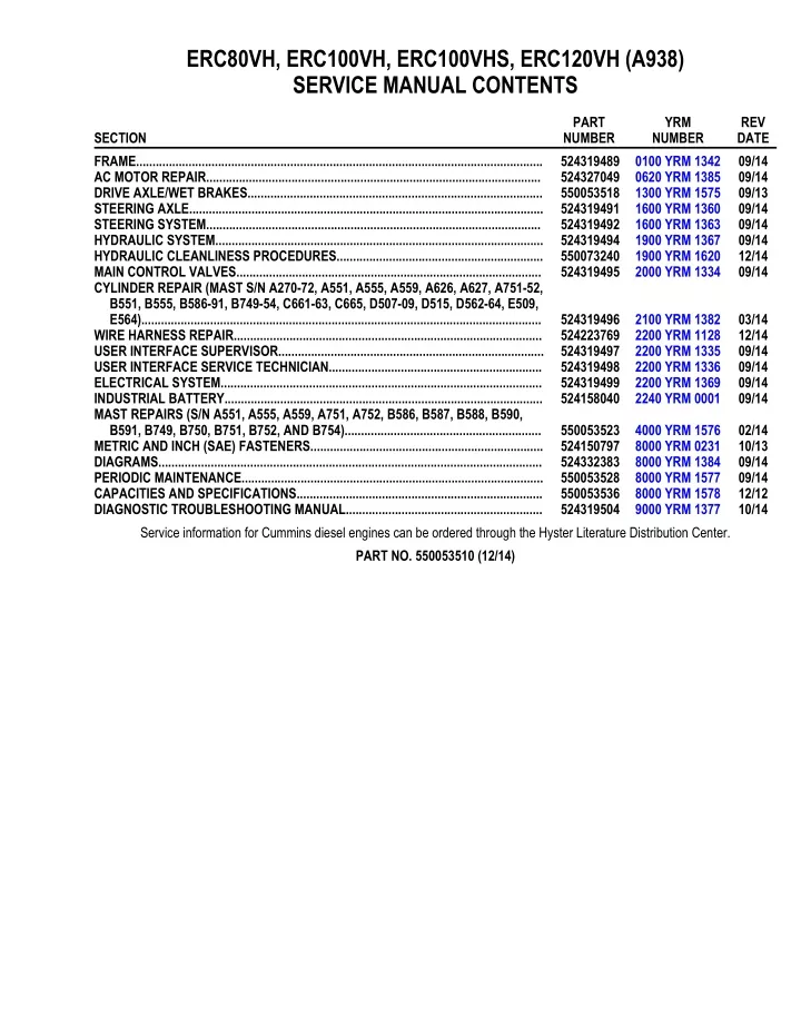
ERC80VH, ERC100VH, ERC100VHS, ERC120VH (A938) SERVICE MANUAL CONTENTS PART NUMBER 524319489 0100 YRM 1342 524327049 0620 YRM 1385 550053518 1300 YRM 1575 524319491 1600 YRM 1360 524319492 1600 YRM 1363 524319494 1900 YRM 1367 550073240 1900 YRM 1620 524319495 2000 YRM 1334 YRM NUMBER REV DATE 09/14 09/14 09/13 09/14 09/14 09/14 12/14 09/14 SECTION FRAME............................................................................................................................ AC MOTOR REPAIR...................................................................................................... DRIVE AXLE/WET BRAKES.......................................................................................... STEERING AXLE............................................................................................................ STEERING SYSTEM...................................................................................................... HYDRAULIC SYSTEM.................................................................................................... HYDRAULIC CLEANLINESS PROCEDURES............................................................... MAIN CONTROL VALVES............................................................................................. CYLINDER REPAIR (MAST S/N A270-72, A551, A555, A559, A626, A627, A751-52, B551, B555, B586-91, B749-54, C661-63, C665, D507-09, D515, D562-64, E509, E564).......................................................................................................................... WIRE HARNESS REPAIR.............................................................................................. USER INTERFACE SUPERVISOR................................................................................. USER INTERFACE SERVICE TECHNICIAN................................................................. ELECTRICAL SYSTEM.................................................................................................. INDUSTRIAL BATTERY................................................................................................. MAST REPAIRS (S/N A551, A555, A559, A751, A752, B586, B587, B588, B590, B591, B749, B750, B751, B752, AND B754)............................................................ METRIC AND INCH (SAE) FASTENERS....................................................................... DIAGRAMS..................................................................................................................... PERIODIC MAINTENANCE............................................................................................ CAPACITIES AND SPECIFICATIONS........................................................................... DIAGNOSTIC TROUBLESHOOTING MANUAL............................................................ Service information for Cummins diesel engines can be ordered through the Hyster Literature Distribution Center. PART NO. 550053510 (12/14) 524319496 2100 YRM 1382 524223769 2200 YRM 1128 524319497 2200 YRM 1335 524319498 2200 YRM 1336 524319499 2200 YRM 1369 524158040 2240 YRM 0001 03/14 12/14 09/14 09/14 09/14 09/14 550053523 4000 YRM 1576 524150797 8000 YRM 0231 524332383 8000 YRM 1384 550053528 8000 YRM 1577 550053536 8000 YRM 1578 524319504 9000 YRM 1377 02/14 10/13 09/14 09/14 12/12 10/14
0100 YRM 1342 General General DESCRIPTION FRAME This section contains a description and service procedures for the parts of the frame. These parts include the frame, counterweight assembly, overhead guard, hood and seat assembly, access panels, and labels. The frame is a single weldment with mounts for: • Counterweight • Overhead guard • Tilt cylinders • Drive axle, or if equipped, transaxle • Floor plate and pedals • Side step and fender weldments • Hood and seat assembly • Front drop-in bulkhead for lift truck models ERC40-55VH, ERC50VHS (ERC80-120VH, ERC100VHS) (A938) Throughout this section, forward will refer to travel in the direction of the forks and left and right will be determined by an operator sitting in the seat facing forward. See Figure 1. See Figure 2 for lift truck models • ERC22-35VG (ERC045-070VG) (A968) See Figure 3 for lift truck models • ERC16-20VA (ERC030-040VA) (A969) See Figure 4 for lift truck models • ERP22-35VL (ERP045-070VL) (A976) See Figure 5 for lift truck models • ERP40-50VM, ERP50-55VM6 (ERP080-120VM, ERP100VML) (A985) A. LEFT SIDE B. RIGHT SIDE C. FORWARD TRAVEL See Figure 6 for lift truck models • ERC40-55VH, ERC50VHS (ERC80-120VH, ERC100VHS) (A938) Figure 1. Truck Orientation If a torque value is not specified, go to Metric and Inch (SAE) Fasteners 8000YRM0231 for torque values. 1
General 0100 YRM 1342 1. FRONT OVERHEAD GUARD MOUNTING BRACKET REAR OVERHEAD GUARD MOUNTING BRACKET COUNTERWEIGHT MOUNTING PLATE FRONT BULKHEAD 5. 6. 7. 8. 9. RIGHT FRAME CHANNEL LEFT FRAME CHANNEL REAR BULKHEAD TILT ANCHOR PLATE SIDE STEP MOUNTING BRACKET 2. 3. 4. Figure 2. Frame Weldment for Lift Truck ERC22-35VG (ERC045-070VG) (A968) 2
0100 YRM 1342 General 1. FRONT OVERHEAD GUARD MOUNTING BRACKET REAR OVERHEAD GUARD MOUNTING BRACKET COUNTERWEIGHT MOUNTING PLATE FRONT BULKHEAD 5. 6. 7. 8. 9. RIGHT FRAME CHANNEL LEFT FRAME CHANNEL REAR BULKHEAD TILT ANCHOR PLATE SIDE STEP MOUNTING BRACKET 2. 3. 4. Figure 3. Frame Weldment for Lift Truck ERC16-20VA (ERC030-040VA) (A969) 3
General 0100 YRM 1342 1. FRONT OVERHEAD GUARD MOUNTING BRACKET OPERATOR MODULE PLATE FRONT BULKHEAD REAR BULKHEAD COUNTERWEIGHT MOUNTING PLATE LEFT FENDER 7. 8. 9. 10. TILT ANCHOR PION 11. DRIVE AXLE MOUNTS 12. SIDE STEP MOUNTING BRACKET RIGHT FENDER RIGHT FRAME CHANNEL LEFT FRAME CHANNEL 2. 3. 4. 5. 6. Figure 4. Frame Weldment for Lift Truck ERP22-35VL (ERP045-070VL) (A976) 4
0100 YRM 1342 General 1. FRONT OVERHEAD GUARD MOUNTING BRACKET OPERATOR MODULE PLATE FRONT BULKHEAD REAR BULKHEAD COUNTERWEIGHT MOUNTING PLATE LEFT FENDER 7. 8. 9. 10. TILT ANCHOR PION 11. DRIVE AXLE MOUNTS 12. SIDE STEP MOUNTING BRACKET RIGHT FENDER RIGHT FRAME CHANNEL LEFT FRAME CHANNEL 2. 3. 4. 5. 6. Figure 5. Frame Weldment for Lift Truck ERP40-50VM, ERP50-55VM6 (ERP080-120VM, ERP100VML) (A985) 5
General 0100 YRM 1342 1. FRONT OVERHEAD GUARD MOUNTING BRACKET REAR OVERHEAD GUARD MOUNTING BRACKET COUNTERWEIGHT MOUNTING PLATE FRONT BULKHEAD 5. 6. 7. 8. 9. RIGHT FRAME CHANNEL LEFT FRAME CHANNEL REAR BULKHEAD TILT ANCHOR PLATE SIDE STEP MOUNTING BRACKET 2. 3. 4. Figure 6. Frame Weldment for Lift Trucks ERC40-55VH, ERC50VHS (ERC80-120VH, ERC100VHS) (A938) The hydraulic and traction motor electronic controllers and contactors are located in the counterweight cavity for the following lift truck models • ERC22-35VG (ERC045-070VG) (A968) • ERC16-20VA (ERC030-040VA) (A969) • ERC40-55VH, ERC50VHS (ERC80-120VH, ERC100VHS) (A938) NOTE: Lift truck models ERC22-35VG (ERC045-070VG) (A968) manufactured after June, 2012 are equipped with a removable floor plate that requires no tools to remove. For all lift truck models covered in this Service Manual, the Vehicle Systems Manager (VSM) is either mounted on or near the front bulkhead underneath the floor mat and floor plate. The hydraulic motor electronic controller and contactor are located in the counterweight cavity and the traction motor controller is attached to the front bulkhead for the following lift truck models • ERP22-35VL (ERP045-070VL) (A976) • ERP40-50VM, ERP50-55VM6 (ERP080-120VM, ERP100VML) (A985) 6
0100 YRM 1342 General DISCHARGING THE CAPACITORS 3. Disconnect the battery by separating the connectors. WARNING DO NOT make repairs or adjustments unless you have been properly trained and authorized to do so. Improper repairs and adjustments can create dangerous operating conditions. DO NOT operate a lift truck that needs repairs. Report the need for repairs to your supervisor immediately. If repair is necessary, attach a DO NOT OPERATE tag on the steering wheel and disconnect the battery. 4. Block the drive wheels to prevent the lift truck from moving. 5. Make sure the Emergency-Disconnect switch HAS NOT been activated. If the Emergency- Disconnect switch is activated, rotate the switch to the right until it pops up. 6. Press horn button. Wait 30 seconds to be sure capacitors are fully discharged. Disconnect the battery and allow the capacitors to discharge before opening any compartment covers or inspecting or repairing the electrical system. DO NOT place tools on top of the battery. If a tool causes a short circuit, the high current flow from the battery can cause personal injury or property damage. RAPID CHARGE All the lift trucks covered in this Service Manual may be equipped with an optional Basic Rapid Charge System. See Figure 7. Lift truck models ERP22-35VL (ERP045-070VL) (A976) and ERP40-50VM, ERP50-55VM6 (ERP080-120VM, ERP100VML) (A985) may also be equipped with an optional Integrated (Quick Disconnect) Rapid Charge System. See Figure 8 or Figure 9. Some checks and adjustments are performed with the battery connected. DO NOT connect the battery until the procedure instructs you to do so. Never wear any metallic items on your fingers, arms, or neck. Metal items can accidentally make an electrical connection and cause injury. On lift trucks equipped with either Rapid Charge System, the battery is charged during operator breaks or when the lift truck is not being used. Both systems provide extended operation with a single battery. Connect or disconnect battery from the Rapid Charge System using the battery connectors. Before performing any tests or adjustments, block the lift truck to prevent unexpected movement. The capacitor in the transistor controller(s) can hold an electrical charge for about 10 seconds after the battery is disconnected. To prevent an electrical shock and personal injury, discharge the capacitor(s) before inspecting or repairing any component in the drive unit compartment. Make certain that the battery has been disconnected. Some of the features of the Basic Rapid Charge System include (see Figure 7): • Battery connector externally mounted for easy access. • Vented side covers for improved battery cooling. • Requires rapid charge vented battery and sealed battery fan box with thermostat. DO NOT short across the motor controller terminals with a screwdriver or jumper wire. Make certain the Emergency-Disconnect switch has not been activated. This will isolate the controller and prevent the capacitors from discharging properly. disconnect the battery is by separating the battery connectors. Some of the features of the Integrated (Quick Disconnect) Rapid Charge System include (see Figure 8 or Figure 9): • Power cables from hood mounted connector are wired to the existing truck battery connections, eliminating the need to run cables from the battery to the top side of hood. • The Integrated Rapid Charge System easily supports rapid, fast, and convenient charging. The proper way to 1. Ensure the capacitors are discharged by performing Step 2 through Step 6 below. 2. Turn the key or keyless switch to the OFF position. 7
General 0100 YRM 1342 • Cutouts in the battery compartment side panel are standard with the Integrated Rapid Charge System and help support vented tray batteries and batteries with side-mounted cooling fans. An interlock switch on the hood mounted connector housing door prevents truck from being operated during charging. • NOTE: LIFT TRUCK MODELS ERP22-35VL (ERP045-070VL) (A976) SHOWN. 1. 2. RAPID CHARGE CONNECTOR VENTED SIDE COVER Figure 7. Basic Rapid Charge System 8
0100 YRM 1342 General 1. 2. 3. SIDE PANEL CUTOUT COVER BATTERY CABLES 4. 5. INTERLOCK SWITCH BATTERY CONNECTOR Figure 8. Integrated (Quick Connect) Rapid Charge System, Lift Truck Models ERP22-35VL (ERP045-070VL) (A976) 9
General 0100 YRM 1342 1. 2. 3. SIDE PANEL CUTOUT COVER BATTERY CABLES 4. 5. INTERLOCK SWITCH BATTERY CONNECTOR Figure 9. Integrated (Quick Connect) Rapid Charge System, Lift Truck Models ERP40-50VM, ERP50-55VM6 (ERP080-120VM, ERP100VML) (A985) GROUND TEST 1. Using an ohm meter, place a test lead at the armrest mounting bolt and another at the truck frame. The resistance needs to read 5 Ohms or less. See Figure 10. NOTE: If the static discharge ground connection is not secured properly, it could lead to the possible failure of the traction motor and/or pump motor controller. 2. If resistance is greater than 5 Ohms, double check installation of seat assembly, both ends of seat wiring harness, and wiring harness ground strap. To ensure proper installation of seat assembly and associated bracketing, perform continuity test as described below: 10
0100 YRM 1342 MUD GUARDS Lift truck models equipped with mud guards will have mud guards attached to front fender extensions and suspended between drive wheels and carriage. The mud guards are not serviceable and should be re- placed if damaged or no longer providing shielding from debris. 1. Set parking brake and turn key or keyless switch to OFF position. 2. Remove capscrew and nut from lift truck frame and fender extension. Discard mud guard. See Figure 11. 3. Install new mud guard, capscrew, and nut into fender extension and frame. Tighten capscrew to 66 N•m (49 lbf ft). NOTE: STANDARD TREAD MUD GUARD SHOWN. WIDE TREAD MUD GUARD IS SIMILAR. A. ARMREST FOR LIFT TRUCK MODELS ERC045-070VG (A968), ERC030-040VA (A969), ERP045-070VL (A976), ERP080-120VM (A985), AND ERC80-120VH, ERC100VHS (A938) B. ARMREST FOR LIFT TRUCK MODELS ERC22-35VG (A968), ERC16-20VA (A969), ERP22-35VL (A976), ERP40-50VM, ERP50-55VM6 (A985), AND ERC40-55VH, ERC50VHS (A938) 1. 2. 3. CAPSCREW NUT MUD GUARD Figure 11. Mud Guards 1. 2. ARMREST BOLT FRAME Figure 10. Ground Test 11
Covers and Floor Plates 0100 YRM 1342 Covers and Floor Plates FOR LIFT TRUCK MODELS ERC22-35VG (ERC045-070VG) (A968) to the frame with capscrews and washers. The manual hydraulic floor plate and e-hydraulic floor plate hook onto the floor plate. See Figure 12. Various covers and floor plates provide access to components during service and securely cover areas during normal operations. 2. Counterweight cover is attached to counterweight by two capscrews and allows access to electrical controllers. See Figure 12. NOTE: (ERC045-070VG) (A968) manufactured after June, 2012 are equipped with a removable floor plate that requires no tools to remove. Lift truck models ERC22-35VG 3. Manual hydraulic covers protect links during oper- ation. For removal procedures for these covers see Main Control Valves 2000YRM1334. See Figure 12. 1. Floor mat and floor plates in operator compart- ment allow access to traction motor, hydraulic pump and motor, service and parking brakes, and hydraulic control valve. The floor plate is fastened 4. Hood latch cover is attached to bulkhead using two capscrews. See Figure 12. A. MANUAL HYDRAULIC CONTROL LEVERS B. E-HYDRAULIC CONTROL LEVERS 1. 2. 3. 4. 5. 6. 7. COUNTERWEIGHT COVER CAPSCREW HOOD LATCH COVER* MANUAL HYDRAULIC COVERS MANUAL HYDRAULIC FLOOR MAT WASHER MANUAL HYDRAULIC FLOOR PLATE 8. 9. 10. E-HYDRAULIC FLOOR PLATE 11. COUNTERWEIGHT 12. FRAME 13. FLOOR PLATE COWL E-HYDRAULIC FLOOR MAT *HOOD LATCH COVER USED ON LIFT TRUCKS EQUIPPED WITH EITHER MANUAL OR E-HYDRAULIC CONTROL LEVERS. Figure 12. Covers and Floor Plates for Lift Truck Models ERC22-35VG (ERC045-070VG) (A968) 12
Thank you very much for your reading. Please Click Here. Then Get COMPLETE MANUAL. NO WAITING NOTE: If there is no response to click on the link above, please download the PDF document first and then click on it.
0100 YRM 1342 Covers and Floor Plates FOR LIFT TRUCK MODELS ERC16-20VA (ERC030-040VA) (A969) 2. Counterweight cover is attached to counterweight by two capscrews and allows access to electrical controllers. See Figure 13. Various covers and floor plates provide access to components during service and securely cover areas during normal operations. 3. Manual hydraulic covers protect links during oper- ation. For removal procedures for these covers see Main Control Valves 2000YRM1334. See Figure 13. 1. Floor mat and floor plates in operator compart- ment allow access to traction motor, hydraulic pump and motor, service and parking brakes, and hydraulic control valve. The floor plate is fastened to the frame with capscrews and washers. The manual hydraulic floor plate and e-hydraulic floor plate hook onto the floor plate. See Figure 13. A. E-HYDRAULIC CONTROL LEVERS B. MANUAL HYDRAULIC CONTROL LEVERS 1. 2. 3. 4. 5. 6. COUNTERWEIGHT COUNTERWEIGHT COVER CAPSCREW FRAME COWL E-HYDRAULIC FLOOR PLATE 7. 8. 9. 10. MANUAL HYDRAULIC FLOOR PLATE 11. MANUAL HYDRAULIC FLOOR PLATE 12. MANUAL HYDRAULIC FLOOR MAT E-HYDRAULIC FLOOR PLATE E-HYDRAULIC FLOOR MAT MANUAL HYDRAULIC COVERS Figure 13. Covers and Floor Plates for Lift Truck Models ERC16-20VA (ERC030-040VA) (A969) 13
Covers and Floor Plates 0100 YRM 1342 FOR LIFT TRUCK MODELS ERP22-35VL (ERP045-070VL) (A976) 2. Counterweight cover is attached to counterweight by a tow pin and two capscrews. This cover al- lows access to electrical controllers, hydraulic pump and motor, and hydraulic tank. See Fig- ure 14. Various covers and floor plates provide access to components during service and securely cover areas during normal operations. 3. Manual hydraulic covers protect links during oper- ation. For removal procedures for these covers see Main Control Valves 2000YRM1334. See Figure 14. 1. Floor mat and floor plates in operator compart- ment allow access to service and parking brakes and hydraulic control valve. The floor plate is fas- tened to the frame with capscrews and washers. The manual hydraulic floor plate and e-hydraulic floor plate hook onto the floor plate. See Fig- ure 14. A. E-HYDRAULIC CONTROL LEVERS B. MANUAL HYDRAULIC CONTROL LEVERS 1. 2. 3. 4. 5. 6. 7. COUNTERWEIGHT FRAME COWL COUNTERWEIGHT COVER TOW PIN CAPSCREW MANUAL HYDRAULIC FLOOR PLATE 8. 9. 10. MANUAL HYDRAULIC COVERS 11. E-HYDRAULIC FLOOR PLATE 12. E-HYDRAULIC FLOOR PLATE 13. E-HYDRAULIC FLOOR MAT MANUAL HYDRAULIC FLOOR PLATE MANUAL HYDRAULIC FLOOR MAT Figure 14. Covers and Floor Plates for Lift Truck Models ERP22-35VL (ERP045-070VL) (A976) 14
0100 YRM 1342 Covers and Floor Plates FOR LIFT TRUCK MODELS ERP40-50VM, ERP50-55VM6 (ERP080-120VM, ERP100VML) (A985) 2. Counterweight cover is attached to counterweight by three captive capscrews. This cover allows ac- cess to hydraulic pump electrical controller, hy- draulic pump and motor, and hydraulic tank. See Figure 15 or Figure 16. Various covers and floor plates provide access to components during service and securely cover areas during normal operations. 3. Manual hydraulic covers protect links during oper- ation. For removal procedures for these covers see Main Control Valves 2000YRM1334. See Figure 15 or Figure 16. 1. Floor mat and floor plates in operator compart- ment allow access to service brakes, hydraulic control valve, and traction motor electrical control- ler. The manual hydraulic floor plate and e-hy- draulic floor plate hook onto the floor plate. See Figure 15 or Figure 16. A. MANUAL HYDRAULIC CONTROL LEVERS B. E-HYDRAULIC CONTROL LEVERS 1. 2. 3. 4. 5. 6. CAPTIVE CAPSCREW COUNTERWEIGHT COVER COUNTERWEIGHT MANUAL HYDRAULIC FLOOR MAT MANUAL HYDRAULIC FLOOR PLATE MANUAL HYDRAULIC FLOOR PLATE 7. 8. 9. 10. E-HYDRAULIC FLOOR MAT 11. E-HYDRAULIC FLOOR PLATE 12. E-HYDRAULIC FLOOR PLATE FRAME MANUAL HYDRAULIC COVERS COWL Figure 15. Covers and Floor Plates for Lift Truck Models ERP40-50VM, ERP50-55VM6 (ERP080-120VM, ERP100VML) (A985) Manufactured Before Nov, 2014 15
Covers and Floor Plates 0100 YRM 1342 A. MANUAL HYDRAULIC CONTROL LEVERS B. E-HYDRAULIC CONTROL LEVERS 1. 2. 3. 4. 5. 6. CAPTIVE CAPSCREW COUNTERWEIGHT COVER COUNTERWEIGHT MANUAL HYDRAULIC FLOOR MAT MANUAL HYDRAULIC FLOOR PLATE MANUAL HYDRAULIC FLOOR PLATE 7. 8. 9. 10. E-HYDRAULIC FLOOR MAT 11. E-HYDRAULIC FLOOR PLATE 12. E-HYDRAULIC FLOOR PLATE FRAME MANUAL HYDRAULIC COVERS COWL Figure 16. Covers and Floor Plates for Lift Truck Models ERP40-55VM (ERP080-120VM ) (A985) Manufactured After Nov, 2014 16
0100 YRM 1342 Overhead Guard Replacement FOR LIFT TRUCK MODELS ERC40-55VH, ERC50VHS (ERC80-120VH, ERC100VHS) (A938) 2. Counterweight cover is attached to counterweight by two capscrews and allow access to electrical controllers. See Figure 17. 3. Manual hydraulic covers protect links during oper- ation. For removal procedures for these covers see Main Control Valves 2000YRM1334. See Figure 17. Various covers and floor plates provide access to components during service and securely cover areas during normal operations. 1. Floor mat and floor plates in operator compart- ment allow access to traction motor, hydraulic pump and motor, service brakes, and hydraulic control valve. The manual hydraulic floor plate and e-hydraulic floor plate hook onto floor plate. See Figure 17. A. MANUAL HYDRAULIC CONTROL LEVERS B. E-HYDRAULIC CONTROL LEVERS 1. 2. 3. 4. 5. 6. CAPSCREW COUNTERWEIGHT COVER COUNTERWEIGHT FRAME MANUAL HYDRAULIC COVERS MANUAL HYDRAULIC FLOOR PLATE 7. 8. 9. 10. E-HYDRAULIC FLOOR PLATE 11. E-HYDRAULIC FLOOR PLATE 12. E-HYDRAULIC FLOOR MAT MANUAL HYDRAULIC FLOOR PLATE MANUAL HYDRAULIC FLOOR MAT COWL Figure 17. Covers and Floor Plates for Lift Truck Models ERC40-55VH, ERC50VHS (ERC80-120VH, ERC100VHS) (A938) 17
Overhead Guard Replacement 0100 YRM 1342 Overhead Guard Replacement REMOVE See Periodic Maintenance 8000YRM1442 for lift truck models • ERC16-20VA (ERC030-040VA) (A969) For Lift Trucks ERC22-35VG (ERC045-070VG) (A968), ERC16-20VA (ERC030-040VA) (A969), and ERC40-55VH, ERC50VHS (ERC80-120VH, ERC100VHS) (A938) See Periodic Maintenance 8000YRM1577 for lift truck models • ERC40-55VH, ERC50VHS (ERC80-120VH, ERC100VHS) (A938) WARNING DO NOT operate lift truck without overhead guard correctly fastened to the lift truck frame. 1. Remove battery from lift truck. See How to Change Battery in the Operating Manual or Pe- riodic Maintenance manual above for proce- dures. WARNING DO NOT weld, drill, grind, or cut the overhead guard for mounts of lights or accessories. The strength of the overhead guard can be reduced. 2. Remove hood and seat assembly from lift truck. See section Hood and Seat Assembly Repair, Remove for procedures. 3. Access to rear capscrews is from the battery com- partment. Remove rear capscrews from rear over- head guard legs and plates. WARNING PUTTING THE LIFT TRUCK ON BLOCKS The lift truck must be put on blocks for some types of maintenance and repair. The removal of the mast, drive axle, battery, or counterweight as- semblies will cause large changes in the center of gravity. When the lift truck is put on blocks, put additional blocks in the following positions: If the mast and drive axle are removed, put blocks under the counterweight so the lift truck cannot fall backward. If the counterweight is removed, put blocks under the mast so that the lift truck cannot fall forward. See Figure 18 for lift truck models • ERC22-35VG (ERC045-070VG) (A968) • ERC16-20VA (ERC030-040VA) (A969) See Figure 19 for lift truck models • ERC40-55VH, ERC50VHS (ERC80-120VH, ERC100VHS) (A938) 4. Remove front capscrews from front overhead guard legs and from the right and left plates. See Figure 18 for lift truck models • ERC22-35VG (ERC045-070VG) (A968) • ERC16-20VA (ERC030-040VA) (A969) Put the lift truck on blocks on a solid, even, and level surface. Verify the blocks or stands have enough capacity to hold the lift truck. Use addi- tional blocks next to the tires as necessary to pre- vent movement of the lift truck. See Figure 19 for lift truck models • ERC40-55VH, ERC50VHS (ERC80-120VH, ERC100VHS) (A938) Verify the lifting devices used during repairs can lift the weight of the parts and assemblies. NOTE: Note routing of electrical wires prior to discon- necting. See the Operating Manual or one of the following service manuals for the procedure to put the lift truck on blocks. NOTE: Tag electrical connectors during removal to aid in installation. 5. Tag and disconnect electrical wires that go through the legs of overhead guard. See Periodic Maintenance 8000YRM1364 for lift truck models • ERC22-35VG (ERC045-070VG) (A968) 18