Download
1 / 21
210 likes | 311 Vues
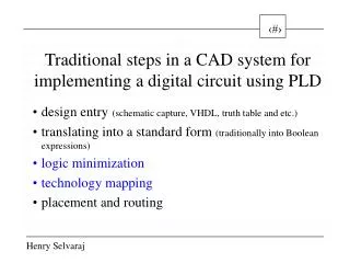
Traditional steps in a CAD system for implementing a digital circuit using PLD. design entry (schematic capture, VHDL, truth table and etc.) translating into a standard form (traditionally into Boolean expressions) logic minimization technology mapping placement and routing.

E N D
Traditional steps in a CAD system for implementing a digital circuit using PLD design entry(schematic capture, VHDL, truth table and etc.) translating into a standard form (traditionally into Boolean expressions) logic minimization technology mapping placement and routing
Some important logic minimization methods decomposition chart technique (Ashenhurst 1959, Curtis 1962), abstract decomposition (Roth - Karp 1962), algebraic and Boolean division methods (Brayton 1982, Abouzeid 1990, Rajski 1992), spectral techniques (Hurst et al. 1985) multiple-level BDD and other decision graph approaches (Brayton 1986) residues based method (McCluskey 1986), decomposition using groupability method (Bochmann et al. 1991), functional decomposition (Perkowski 1992, Sasao 1993), balanced multi-level functional decomposition using symbolic decomposition concept (Selvaraj, Luba 1994)
Why decomposition? Minimization techniques concentrate on minimizing the number of terms in an expression. The only restriction imposed by FPGA is the number of inputs
How to take it in? What is decomposition? Decompose!
Ashenhurst, in his fundamental paper, stated the disjunctive decomposition theorem based on the notion of decomposition charts. Curtis extended the Ashenhurst's results to multiple decomposition when F is expressed as F = H(A, G1(B),...,Gk(B)). They were the first to introduce the concept of functional decomposition.
In the early 80's, functional decomposition methods lost their importance because of the rapid development of synthesis techniques referred to as division based methods. Algebraic division of sum-of-products expressions represented by the sets of cubes became a basic operation in the procedures of substitution and kernel extraction used for decomposition of Boolean functions
Since the late 80's logic decomposition has been again attracting some attention as a technique used for design of PLAs. Devadas et al. proposed Boolean decomposition of a PLA into two cascaded PLAs.
Functional decomposition can play an important role in the design of FPGA-based circuits because their structure imposes constraints on the number of inputs only and the two-level minimization is not needed. However, the division based synthesis became so deeply rooted that earlier synthesis methods for FPGAs were based on the multilevel minimization approach.
Recollection of useful definitions: A Boolean variable is a single co-ordinate in a Boolean space. A literal is a Boolean variable or its complement. A cube c is a set of literals such that x c x’ c. Two trivial cubes 0 and 1 exist. They are defined as the Boolean functions 0 and 1 respectively. A Boolean expression is a set of cubes.
Definitions contd.. A Boolean expression is called non redundant if no cube of the expression properly contains an another cube. For example, a + ab is redundant because {a} {a,b}. The expression a + b is not redundant.
Definitions contd.. The support is the set of Boolean variables which appear either complemented or uncomplemented in the expression f. Two functions f and g are said to have a disjoint support if and only if sup(f) sup(g) = .
Definitions contd.. An incompletely specified single-output function F is represented by a triplet of completely specified single-output functions: F(f,d,r), where f represents the ON-set, i.e. all input vectors for which F evaluates to 1. Similarly, d and r are representations of the don't care set and the OFF-set, respectively.
Definitions contd.. The product of two expressions f and g (denoted fg) is defined as fg = {ci dj ci f dj g}.
Basic Notions A Boolean function F of n binary variables x1,..xn can be expressed as: F: Dn {0,1,-}m,where '-' is called a 'don't care'. If the function F is expressed as F:{0,1}n {0,1}m, then it is called a completely specified function. A function with a single output (i.e. m = 1), is called a unitary function and isdenoted by f. On the other hand, if the number of outputs is more than one, the function is called a group of (unitary) functions and is denoted by F.
Basic notions contd... An element of the set Dn is called a minterm (sometimes known as input vector) and its respective output is called an output vector. The tabular representation of minterms and their respective output vectors generated by the function F is called a truth table. In general, the truth table does not contain input vectors v, for which all the outputs assume 'do not care' values. Hence some authors define the function F simply as: F: Dn {0,1}m, where Dn {0,1}n.
Basic notions contd... The basic requirement of a multilevel logic synthesis is to implement a function F as a logic circuit, i.e. into a set of elements transforming the binary vectors Dn {0,1,-,}m. However, considering the wide spectrum of technological possibilities, it is not necessary to be more specific about the expressions 'logic circuit' and 'set of elements'. They can be understood according to the demand of the circumstances. But it is important to realize that an implementation can be a multilevel implementation also. Hence concrete distinction of input and output variables is valid only at the initial specification level.
Basic notions contd... Consider a tuple T = (M,A,X,Y), where: M - non empty finite set of minterms. A - finite set of arguments a (X is the set of input variables and Y is the set of output variables); A = X Y and X Y = , where for each a A, a - function which maps the arguments into their values for every minterm v M, i.e.: a: M VA,VX = {0,1}, VY = {0,1,-}.
Basic notions contd... As every pair of minterms in the specification table T may have certain identical inputs, a convenient form of expressing such an 'identity' is an indiscernibility relation. This relation, called IND relation, can be defined as follows for the requirements of Boolean functions: Definition: Let B X and v1,v2 M. Minterms (v1,v2) belong to IND(B) if and only if for every x B, x(v1) = x(v2).
Basic notions contd... Therefore, the IND relation divides the set M into M/IND(B) abstract equivalence classes. In further analysis, for simplicity reasons, the abstract classes M/IND(B) are denoted as P(B) and called as the input partitions generated by the set B. So, the equation can be rewritten as: P(B) = P(x) xB where denotes the product of input partitions for every x B.
Basic notions contd... Two output vectors p and q are said to be consistent if their respective components, which are defined, are equal: i {n+1,...,n+m}, (pi = qi) (pi = -) (qi = -) Consistency relation of the output vectors is denoted by p ~ q. For example, if p = (00-), q = (-01) and r = (0-0), it is said that p ~ q, p ~ r and q _ r (q is inconsistent with r).
Basic notions contd... Every consistent pair of input vectors p,q (p,q {0,1,-}m) has its product vector r defined as r = pq = (r1,...,rn), where the component ri is: 0 if pi, qi are respectively 0,0; 0,-; -,0; 1 if pi, qi are respectively 1,1; 1,-; -,1; - if pi, qi are respectively -,-. For example if p = (0-1-) and q = (--10), then their product vector r = pq = = (0-10).