Download
1 / 48
790 likes | 1.71k Vues
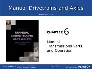
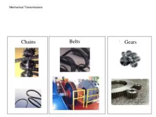
Manual Transmissions. Sliding Gear Transmission Old school, used from late 1800’s to 1940’s? Has two or more shafts in parallel with sliding spur gears. Sliding Gear Transmission If either gear is rotating, shifting is difficult and gear “clashing” will result.

E N D
Sliding Gear Transmission • Old school, used from late 1800’s to 1940’s? • Has two or more shafts in parallel with sliding spur gears.
Sliding Gear Transmission • If either gear is rotating, shifting is difficult and gear “clashing” will result. • Some manufacturers may still have a sliding gear for reverse.
Collar-shift Transmission • Has two parallel shafts with gears in constant mesh • These “collars” slide on a hub that is splined to the output shaft, thus transferring power. • Gear “clashing” will occur if the gear speeds are not matched by double clutching.
Double Clutching • The shifter, rather than going straight to the next gear, makes a stop in neutral and then the clutch is released. • This is to allow the engine to slow down (or with a tap on the gas, speed up when downshifting) so the transition into the next gear is much more smooth. • The driver then depresses the clutch again and completes the shift into the target gear, and finally the clutch is released again, putting the car back into gear.
Synchromesh Transmissions • Gears are in constant mesh and are collar shifted • All forward gears are of a helical design
Synchromesh Transmissions • Collars are equipped with synchronizers • Synchronizers eliminate the need to equalize gear speeds before engagement • Used on all current models of cars – may use a spur gear for reverse
Synchromesh Transmissions • Engine torque is applied to the input shaft (clutch shaft) when the clutch is engaged. • The input shaft is fitted with a gear (input gear or clutch gear)
Synchromesh Transmissions • The front of the output shaft is machined to accept a bearing that fits into the input-shaft. • The different speed gears (1st, 2nd, 3rd 4th, etc.) rotate on the main shaft.
Synchromesh Transmissions • Parallel to (below or beside) the input and output main shaft is the counter shaft • The counter shaft is fitted with different sized gears.
Synchromesh Transmissions • All of these gears are in constant mesh with the gears on the output shaft except … • One gear is in constant mesh with the input shaft gear.
Synchromesh Transmissions • Gear changes occur when the selected gear is connected to the output shaft. • This is accomplished by locking a collar onto the selected gear. • The collars are moved by shift forks.
Synchronizers • Bring components that are rotating at different speeds to one synchronized speed • The four types of synchronizers are: • Block (most common type used today) • Disc and plate • Plain • Pin
Block Synchronizer Assembly • Hub • Sleeve • Blocking ring • Inserts or spring-and-ball detent devices
Synchronizer Hub • The hub is is internally splined to the mainshaft • The inserts slide back and forth in slots on the hub. • Some inserts use a ridge to detent the slide with an internal groove on the sleeve.
Synchronizer Insert Other inserts are of a ball and spring design
Synchronizer Sleeve • The sleeve surrounds the synchronizer assembly • Internal splines mesh with the outside splines of the hub • The sleeve is internally grooved perpendicular to the splines to catch the ridge of the insert
Synchronizer Sleeve The outside of the sleeve is also grooved to accept the shift fork
Blocking Rings Bronze or brass blocking rings are found at the front and rear of the synchronizer assembly.
Blocking Rings • …are notched to accept the insert keys on the hub. • Thus the blocking ring and hub turn at the same speed.
Blocking Rings • Beveled dog teeth are found on the driven gear and the blocking ring. These are used for alignment during shifting. • The inside of the blocking ring is shaped like a cone to mate with the conical shoulder of the driven gear.
Blocking Rings • The inside of the blocking ring’s surface contains sharp grooves. • These grooves disperse oil to maximize friction between the ring and gear.
Synchronizer Operation • First, the sleeve is moved toward the gear by the shift lever and engages the hub assembly • Second, the movement of the sleeve causes the inserts to press the blocking ring onto the cone of the gear
Synchronizer Operation • Third, when the components reach the same speed, the synchronizer sleeve slides over external dog teeth on the blocking ring and over the dog teeth of the speed gear’s shoulder. This action locks the gear to the main shaft.
Advanced Synchronizer Designs • New materials are being introduced for blocking rings including powdered and organic materials. • Manufactures are also using double and triple cone designs to maximize friction and reduce wear.
Transmission Types • Three-speed transmission • Third gear is direct drive (1:1 ratio) • They are rarely used today • Four-speed transmission • Fourth gear is direct drive (1:1 ratio) • The additional speed ratio is usually between first and second gear • A third hub and sleeve assembly is added to provide for reverse
Transmission Types • Five-speed transmission • a four-speed transmission with an overdrive • helps increase fuel mileage and engine life • Six-speed • Found on performance cars
Transmission Types • Overdrive units: • Popular before advent of four-, five-, and six-speed transmissions
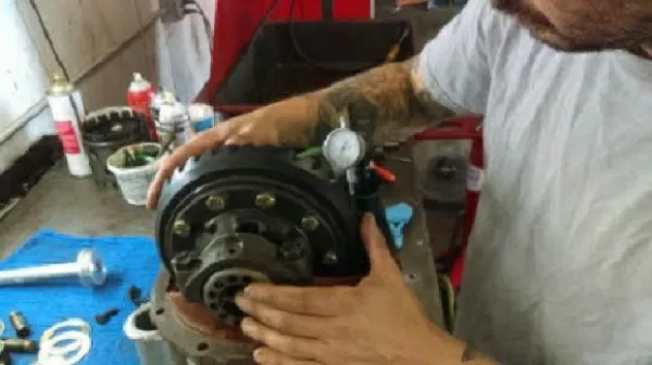
Transmission Components External
Transmission Components Input Shaft
Transmission Operation • Power flow in neutral • The input shaft drives the counter shaft • All of the gears on main shaft rotate • The synchronizers are not engaged with any gear • No power is transferred to the output shaft
Power flow in first gear • The power enters the transmission through the input shaft • The first/second synchronizer sleeve is engaged with the first gear dog teeth • The power is transferred from the input shaft, through the countershaft, and up to the first gear • The first gear drives the output shaft
Power flow in second gear • The power enters the transmission through the input shaft • The first/second synchronizer sleeve is engaged with the secondgear dog teeth • The power is transferred from the input shaft, through the countershaft, and up to the second gear • The secondgear drives the output shaft
Power flow in third gear • The power enters the transmission through the input shaft • The third/fourth synchronizer sleeve is engaged with the third gear dog teeth • The power is transferred from the input shaft, through the countershaft, and up to the thirdgear • The thirdgear drives the output shaft
Power flow in fourth gear • The power enters the transmission through the input shaft • The third/fourth synchronizer sleeve is engaged with the fourth gear dog teeth • The power is transferred from the input shaft to the fourth gear • The fourthgear drives the output shaft
Power flow in fifth gear • The power enters the transmission through the input shaft • The fifth gear synchronizer sleeve is engaged with the fifth gear dog teeth • The power is transferred from the input shaft, through the countershaft, and up to the fifth gear • The fifth gear drives the output shaft in overdrive
Power flow in reverse gear • The power enters the transmission through the input shaft • The reverse gear synchronizer sleeve is engaged with the reverse gear dog teeth • The power is transferred from the input shaft, through the countershaft, through the reverse idler gear, and up to the reverse gear • The reverse gear drives the output shaft in reverse