Horizontal Alignment
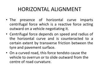
Horizontal Alignment. Horizontal Alignment. Objective: Geometry of directional transition to ensure: Safety Comfort Primary challenge Transition between two directions Fundamentals Circular curves Superelevation or banking. Δ. Vehicle Cornering.


Horizontal Alignment
E N D
Presentation Transcript
Horizontal Alignment • Objective: • Geometry of directional transition to ensure: • Safety • Comfort • Primary challenge • Transition between two directions • Fundamentals • Circular curves • Superelevation or banking Δ
Vehicle Cornering Centripetal force parallel to the roadway Fc Fcn Fcp W Wn Ff Side frictional force Wp Ff Weight parallel to the roadway
Vehicle Cornering Fc α Fcn Fcp α W Wn Ff Wp Ff α Vehicle weight and centripetal force normal to roadway
Vehicle Cornering Rv ≈ Fc α Fcn Fcp α W Wn Ff Wp Ff α
Horizontal Curve Fundamentals PI L PT PC R R Curve is a circle, not a parabola
Superelevation • Banking • number of vertical feet of rise per 100 ft of horizontal distance • e = 100tan α
Superelevation Divide both sides by Wcos(α)
Minimum radius that provides for safe vehicle operation Given vehicle speed, coefficient of side friction, gravity, and superelevation Rv because it is to the vehicle’s path (as opposed to edge of roadway) Superelevation
Selection of e and fs • Practical limits on superelevation (e) • Climate • Constructability • Adjacent land use • Side friction factor (fs) variations • Vehicle speed • Pavement texture • Tire condition • Maximum side friction factor is the point at which tires begin to skid. • Design values are chosen below maximum.
WSDOT Design Side Friction Factors For Open Highways and Ramps from the 2005 WSDOT Design Manual, M 22-01
Design Superelevation Rates - AASHTO from AASHTO’s A Policy on Geometric Design of Highways and Streets 2004
Design Superelevation Rates - WSDOT emax = 8% from the 2005 WSDOT Design Manual, M 22-01
Example 5 A section of SR 522 is being designed as a high-speed divided highway. The design speed is 70 mph. Using WSDOT standards, what is the minimum curve radius (as measured to the traveled vehicle path) for safe vehicle operation?
Example 5 A section of SR 522 is being designed as a high-speed divided highway. The design speed is 70 mph. Using WSDOT standards, what is the minimum curve radius (as measured to the traveled vehicle path) for safe vehicle operation? For the minimum curve radius we want the maximum superelevation. WSDOT max e = 0.10 For 70 mph, WSDOT f = 0.10
Horizontal Curve Fundamentals PI T Δ E M L Δ/2 PT PC R R Δ/2 Δ/2
Horizontal Curve Fundamentals Degree of curvature: Angle subtended by a 100 foot arc along the horizontal curve A function of circle radius Larger D with smaller R Expressed in degrees PI T Δ E M L Δ/2 PT PC R R Δ/2 Δ/2
Horizontal Curve Fundamentals PI Tangent length (ft) T Δ E M L Δ/2 PT PC R R Length of curve (ft) Δ/2 Δ/2
Horizontal Curve Fundamentals PI External distance (ft) T Δ E M L Δ/2 PT PC Middle ordinate (ft) R R Δ/2 Δ/2
Example 4 A horizontal curve is designed with a 1500 ft. radius. The tangent length is 400 ft. and the PT station is 20+00. What is the PC station? T = Rtan(delta/2). Delta = 29.86 degrees D = 5729.6/R, D = 3.82 degrees L = 100(delta)/D = 100(29.86)/3.82 = 781 ft. PC = PT – L = 2000 – 781 = 1219 = 12+19
Stopping Sight Distance SSD (not L) Looking around a curve Measured along horizontal curve from the center of the traveled lane Need to clear back to Ms (the middle of a line that has same arc length as SSD) Ms Obstruction Rv Δs Assumes curve exceeds required SSD
Stopping Sight Distance SSD (not L) Ms Obstruction Rv Δs
Example 6 A horizontal curve with a radius to the vehicle’s path of 2000 ft and a 60 mph design speed. Determine the distance that must be cleared from the inside edge of the inside lane to provide sufficient stopping sight distance. SSD=566 ft (table 3.1) Ms=20.01 ft degrees
Superelevation Transition from the 2001 Caltrans Highway Design Manual
Spiral Curves No Spiral Spiral from AASHTO’s A Policy on Geometric Design of Highways and Streets 2004
Spiral Curves • Ease driver into the curve • Think of how the steering wheel works, it’s a change from zero angle to the angle of the turn in a finite amount of time • This can result in lane wander • Often make lanes bigger in turns to accommodate for this
Spiral Curves • WSDOT no longer uses spiral curves • Involve complex geometry • Require more surveying • If used, superelevation transition should occur entirely within spiral
Operating vs. Design Speed 85th Percentile Speed vs. Inferred Design Speed for 138 Rural Two-Lane Highway Horizontal Curves 85th Percentile Speed vs. Inferred Design Speed for Rural Two-Lane Highway Limited Sight Distance Crest Vertical Curves