Voltage Regulation
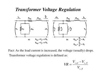
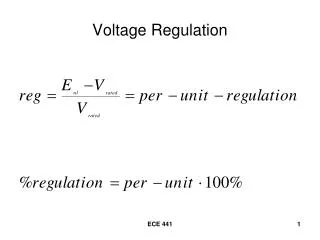
Voltage Regulation. Voltage Regulation (continued). E nl = no-load output voltage Measure with a voltmeter when no load is connected to the transformer

Voltage Regulation
E N D
Presentation Transcript
Voltage Regulation ECE 441
Voltage Regulation (continued) • Enl = no-load output voltage • Measure with a voltmeter when no load is connected to the transformer • Vrated = voltmeter reading at the output terminals when the transformer is supplying the rated apparent power • These voltages are all either High-side or Low-side voltages! ECE 441
Voltage Regulation (continued) • Measurements are not always easy to make, so use the equivalent circuit. ECE 441
When the breaker is open, no current flows in Req,LS , jXeq,LS , or ZLOAD,LS , therefore Vout = VLS = E’LS = Enl ECE 441
With rated load on the secondary, E’LS = ILSZeq,LS + VLS ILS = rated low-side current at a specified power factor VLS = rated low-side voltage Zeq,LS = equivalent impedance of the transformer referred to the low-side E’LS = no-load low-side voltage ECE 441
Example 2.7 • The equivalent low-side parameters of a 250kVA, 4160 – 480V, 60 Hz transformer areReq,LS = 0.00920 Ω and Xeq,LS = 0.0433 Ω. The transformer is operated in the step-down mode and is delivering rated current at rated voltage to a 0.840 power-factor lagging load. • Determine ECE 441
the no-load voltage • The actual input voltage on the high-side • The high-side current • The input impedance • The voltage regulation • The voltage regulation if the power factor of the load is 0.840 leading • Sketch the tip-to-tail phasor diagram of the secondary circuit for the 0.840 power factor lagging load. Show all voltage drops. ECE 441
Low-Side Output ECE 441
The high-side current The input impedance ECE 441
The voltage regulation ECE 441
Voltage Regulation if the power factor is 0.840 leading Regulation is negative because of a voltage rise in the transformer due to resonant effects. ECE 441
The “tip-to-tail” phasor diagram for the 0.840 power factor lagging load. ECE 441
Component Phasors ECE 441
Tip-to-Tail Addition ECE 441