Download
1 / 34
370 likes | 854 Vues
Distribution Feeder Voltage Regulation and Control. W. H. Kersting Milsoft Utility Solutions. Purpose of This Paper. Present ANSI Voltage Standards Present Step Voltage Regulator What it is Control Settings Model IEEE 13 Node Test Feeder Steps in regulating voltage on the test feeder.

E N D
Distribution Feeder Voltage Regulation and Control W. H. Kersting Milsoft Utility Solutions
Purpose of This Paper • Present ANSI Voltage Standards • Present Step Voltage Regulator • What it is • Control Settings • Model • IEEE 13 Node Test Feeder • Steps in regulating voltage on the test feeder
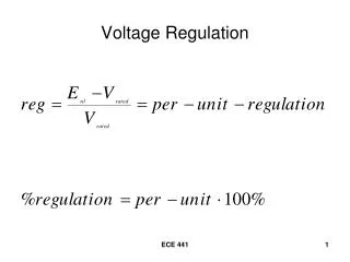
The ANSI Voltage Standards • Range A • Nominal Utilization Voltage = 115 volts • Maximum Utilization Voltage = 126 volts • Minimum Service Voltage = 114 volts • Minimum Utilization Voltage = 110 volts • Range B • Nominal Utilization Voltage = 115 volts • Maximum Utilization Voltage = 127 volts • Minimum Service Voltage = 110 volts • Minimum Utilization Voltage = 107 volts
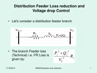
Voltage Drop Assumptions • 1 Volt drop on the service drop • 2 Volt drop on the secondary • 3 Volt drop through the transformer • Minimum Voltage at the Transformer Primary Terminals will be 120 volts
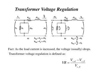
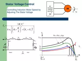
Regulator Control Settings • Voltage Level – voltage to hold at the regulation point • R and X setting (volts) – Equivalent impedance from the regulator to the regulation point • Time Delay – time after a tap change required before the tap is changed • Bandwidth – allowed deviation from the set voltage level
Modifications • Line 4-12 changed to phases B-C • Transformer 6-7 changed to Ungrounded Wye – Delta • Load at Node 7 converted to Delta-PQ • Load at Node 8 converted to Delta-PQ • Load at Node 14 changed to phase B with constant Z load • Load added at Node 5: 300 + j145.3 kVA
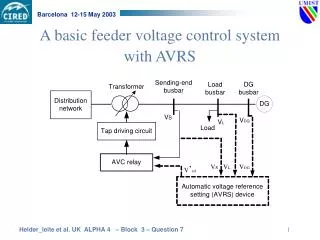
Step 1 • Select regulation point to be Node 4 • Run power-flow with source set to 126 volts • Display Voltage Profile • Compute compensator impedance
Observations • Regulator taps • Phase a: 11 • Phase b: 12 • Phase c: 15 • Concern about high voltage at Node 2 • Need to add shunt capacitors
Shunt Capacitors • Source reactive power • Phase A: 765 kvar • Phase B: 809 kvar • Phase C; 1105 kvar • Install shunt capacitors • Node 3: 100 kvar per phases a,b,c • Node 4: 600 kvar per phases a,b,c • Node 13: 150 kvar on phase c
Observations • Regulator taps • Phase a: 5 • Phase b: 6 • Phase c: 7 • Notice good voltage balance • All voltages between 120 and 122 volts at Node 4