Advanced Control Strategies for Fuel-to-Air Ratio in Engine Management Systems
This research presents model-based control methods aimed at optimizing fuel-to-air ratio (F/A) in engine systems, addressing stringent future emission and diagnostic regulations. The study analyzes dynamic phenomena such as fuel and air mixing, cycle delays from piston strokes, and exhaust travel time to sensors. A system block diagram illustrates controller design enhancements, employing proportional, derivative, and integral controls to improve rise time, reduce overshoot, and eliminate steady-state error. MATLAB syntax for the Padé approximation is also discussed for modeling time delay effects in this context.

Advanced Control Strategies for Fuel-to-Air Ratio in Engine Management Systems
E N D
Presentation Transcript
Fuel to Air Ratio Controller Team Members • Hammad Abbasi • Gurbinder Parmar • Solomon Desta • Madhav Khanna • Sachna Bobal
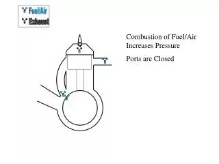
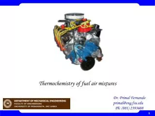
Abstract Model-based control methods designed to meet future emission and diagnostic regulations has increased the need for engine models. Dynamic phenomena affecting the relationship between the sensed F/A output from the exhaust and the fuel-metering command at the input of carburetor are Intake fuel and air mixing Cycle delays due to the piston strokes in the engine The time required for the exhaust to travel from the engine to the sensor.
Controller Design • Add proportional control » » improve Rise Time • Add derivative control » » improve Overshoot • Add integral control » » eliminate ess Initial Assumptions: • Linear sensor output
Padé approximation • Laplace transform » » exp (-sTa) • Pade approximates time delays by rational LTI models • Such approximations useful » » model time delay effects MATLAB Syntax • [num,den] = pade(T,N) • pade(T,N) • sysx = pade(sys,N) • sysx = pade(sys,NI,NO,Nio) • NI(j) » » approximation order for the j-th input channel. • NO(i) » »approximation order for the i-th output channel. • Nio(i,j) » »approximation order for the I/O delay from input j to output i.