Cameras
Cameras. Course web page: vision.cis.udel.edu/cv. March 22, 2003 Lecture 16. Announcements. Read Forsyth & Ponce, Chapter 3-3.3 on camera calibration for Monday HW3: Some image sizes have been reduced and you don’t have to try as many window sizes. Outline. Lenses

Cameras
E N D
Presentation Transcript
Cameras Course web page: vision.cis.udel.edu/cv March 22, 2003 Lecture 16
Announcements • Read Forsyth & Ponce, Chapter 3-3.3 on camera calibration for Monday • HW3: Some image sizes have been reduced and you don’t have to try as many window sizes
Outline • Lenses • Discretization effects of image capture
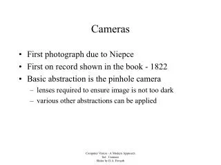
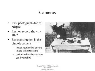
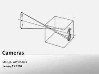
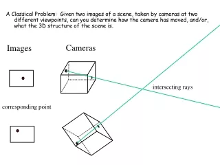
Ideal Pinhole Camera from Forsyth & Ponce Each point on the image plane collects light along one ray from the scene
Real Pinhole Cameras • Problems • Pinholes don’t let through much light ! Dimness/exposure time trade-off • A bigger hole (aka aperture) means that each image point sees a disk of scene points, whose contributions are averaged ! Blurring • Very small apertures introduce diffraction effects from Forsyth & Ponce
Hole too big: Blurring Hole too small: Diffraction from Forsyth & Ponce Real pinhole camera images
Lenses • Benefits: Increase light-gathering power by focusing bundles of rays from scene points onto image points from Forsyth & Ponce
courtesy of Wolfram Refraction • Definition: Bending of light ray as it crosses interface between media (e.g., air ! glass or vice versa) • Index of refraction (IOR) n for a medium: Ratio of speed of light in vacuum to that in medium • By definition, n¸ 1 • Examples: 1¼ nair<nwater<nglass µ1: Angle of incidence µ2: Angle of refraction
courtesy of Wolfram Snell’s Law • The relationship between the angle of incidence and the angle of refraction is given by:
divergence convergence Snell’s Law: Implications • Since µ/sinµ over the range [0, ¼/2] and the angle of refraction is given by we can infer the following from their IORs: n1<n2)µ2<µ1 and n1>n2)µ2>µ1 Son1<n2 in this image courtesy of Wolfram
Converging Light Rays n1 n2 n1<n2
courtesy of Prentice-Hall Redirecting Light • Prisms: Light traveling from a low IOR medium to a high IOR medium and back again is bent by an amount proportional to the apex angle
Focusing Light with Prisms courtesy of S. Majewski
Focusing Light with Prisms: Many Beams courtesy of S. Majewski Light rays intersecting the prisms at different locations have different angles of incidence and thus wind up with different focal points
Lenses as Compound Prisms courtesy of S. Majewski We can get the light rays to have a common focus by gradually widening the effective apex angle as we get farther from the center of the lens
focus focus Thin Lenses • Properties • A ray entering the lens parallel to the optical axis goes through the focus on the other side • A ray entering the lens from the focus on one side emerges parallel to the axis on the other side optical axis courtesy of MTSU
Thin Lens Image Projection z courtesy of U. Colorado
Thin Lens Model from Forsyth & Ponce
Depth of Field • The thin lens equation implies that scene points at different distances from the lens are in focus at different image distances • Only a given range of object distances produce acceptable sharpness
Field of View from Forsyth & Ponce FOV is defined as 2Á, where Á = tan-1d/2f
Lens Problems • Limited depth of field • Radial, tangential distortion: Straight lines curved • Vignetting: Image darker at edges • Spherical aberration • Chromatic aberration: Focal length function of wavelength
Analog Digital • Sampling Aliasing • Quantization Banding • Limited dynamic range Saturation • Temporal integration Motion blur • Noise 1/30th sec. exposure
Sampling • Limited spatial resolution of capture devices results in visual artifacts (i.e., aliasing) • Nyquist theorem: Must sample 2x highest frequency component of signal to reconstruct adequately
High Dynamic Range Panoramas Under- and over-exposed mosaic HDR mosaic courtesy of D. Lischinski