Chapter5 Hardware Description Languages
Chapter5 Hardware Description Languages. ( 硬件描述语言 ). REF. 5.1 5.4. Outline. What & Why HDL? Verilog HDL 模块的概念与结构 标识符、数的表示、数的类型 运算符号 逻辑模块的描述方式 结构描述方式、数据流描述方式 Abstraction Levels Gates Dataflow Proceedural Examples. What & Why HDL?. Hardware Description Language(HDL)

Chapter5 Hardware Description Languages
E N D
Presentation Transcript
Chapter5 Hardware Description Languages (硬件描述语言) REF. 5.1 5.4
Outline • What & Why HDL? • Verilog HDL • 模块的概念与结构 • 标识符、数的表示、数的类型 • 运算符号 • 逻辑模块的描述方式 • 结构描述方式、数据流描述方式 • Abstraction Levels • Gates • Dataflow • Proceedural • Examples
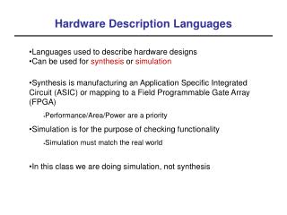
What & Why HDL? • Hardware Description Language(HDL) • A software programming language used to model the intended operation of a piece of hardware • Why HDL? • Text-based design rather than Schematic design • ASIC complexity increase • faster time-to-market • Simulation • Logic Synthesis • Words are better than pictures • PLD, CPLD and FPGA became inexpensive and commonplace
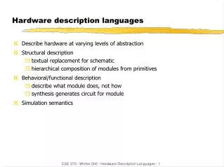
What is need for Hardware Description Language? • Model, Represent, And Simulate Digital Hardware • Hardware Concurrency • Parallel Activity Flow • Semantics for Signal Value And Time • Special Constructs And Semantics • Edge Transitions • Propagation Delays • Timing Checks
History of HDL • First HDL • PALASM, 1980s--Logic equation • Then more complex (minimization, if-then-else statement) • CUPL (Complier Universal for Programmable Logic) • ABEL (Advanced Boolean Equation Language) • Verilog HDL • VHDL represents another high level language for digital system design. • VHDL = VHSIC HDL • VHSIC = Very High Speed Integrated Circuit
HDLs • Software: Assembler high-level language, like C, C++, Java • Hardware: block diagram & schematic HDL • Efficient Large, complex, abstraction • HDL Tool Suits • Text editor • Complier • Synthesizer • Simulator • Template generator • Schematic viewer • Translator • Timing analyzer • Back annotator
功能要求 行为设计(VHDL) 否 行为仿真 是 综合、优化——网表 否 时序仿真 是 布局布线——版图 后仿真 否 是 程序烧写 Design flow 设计创意 + 仿真验证
Gate Behavioral Switch Behavioral Introduction to Verilog HDL • Originally designed in 1983/1984 as a proprietary verification/simulation • IEEE standard 1364 in 1995 • Similar to C language • 4 value logic (0, 1, x, z) • HDL which provides a wide range of levels of abstraction • Architectural, Algorithmic, RTL, Gate, Switch • Mixed level modeling and simulation • Description of digital systems only • Interactive usage • Hierarchical specification
History • 1981 • Gateway Design Automation was founded • Phil Mooby make GHDL(GenRad’s HDL) and HILO simulator • 1983 • Gateway released the Verilog HDL and simulator • 1985 • The language and simulator were enhanced and renamed to “Verilog-XL” • 1988 synopsys make Verilog synthesis tool • 1989 • Cadence bought Gateway • 1995 • The Verilog HDL was adopted as IEEE standard 1364 • i.e. Verilog-1995 • 1997, Verilog-2001
System Specification Suitable for all levels Behavioral level Not suitable HW/SW Partition Hardware Spec Softwre Spec ASIC Boards & Systems FPGA Software PLD Std Parts Application Areas of Verilog
Increasing level of abstraction behavioral (non-structural) gate/switch (structural) Verilog Spans a Wide Range of Modeling Levels • Architectural • Algorithmic • RTL • Gate • Switch
Top Level Module Full Adder Sub-Module 1 Sub-Module 2 Half Adder Half Adder Basic Module 1 Basic Module 2 Basic Module 3 Hierarchical Design E.g. • Concurrency • Structure • Procedural Statements • Time
User Identifiers • Formed from {[A-Z], [a-z], [0-9], _, $}, but .. • .. can’t begin with $ or [0-9] • myidentifier☺ • m_y_identifier☺ • 3my_identifier☻ • $my_identifier☻ • _myidentifier$☺ • Case sensitivity • myid Myid
Modules declaration modulefull_add (A, B, CI, S, CO) ; input A, B, CI ; output S, CO ; wire N1, N2, N3; half_add HA1 (A, B, N1, N2), HA2 (N1, CI, S, N3); or P1 (CO, N3, N2); endmodule modulehalf_add (X, Y, S, C); input X, Y ; output S, C ; xor (S, X, Y) ; and (C, X, Y) ; endmodule
Comments • // The rest of the line is a comment • /* Multiple line comment */ • /* Nesting /*comments */do NOT work */ • Verilog Value Set • 0represents low logic level or false condition • 1 represents high logic level or true condition • x represents unknown logic level • z represents high impedance logic level
No of bits Binary b or B Octal o or O Decimal d or D Hexadecimal h or H Consecutive chars 0-f, x, z Represent the same number Numbers in Verilog (i) <size>’<radix> <value> • 8’h ax = 1010xxxx • 12’o 3zx7 = 011zzzxxx111 • You can insert “_”for readability • 12’b 000_111_010_100 • 12’b 000111010100 • 12’o 07_24
Numbers in Verilog (ii) • Bit extension • MS bit = 0, x or z extend this • 4’b x1 = 4’b xx_x1 • MS bit = 1 zero extension • 4’b 1x = 4’b 00_1x • If size is ommitted it • is inferred from the valueor • takes the simulation specific number of bits or • takes the machine specific number of bits • If radix is ommitted too .. decimal is assumed • 15 = <size>’d 15
Data Types • Nets • Connectsbetween hardware elements • Must be continuously driven by • Continuous assignment (assign) • Module or gate instantiation (output ports) • Default initial value for a wire is “Z” (and for a trireg is “x”) • Registers • Represent data storage elements • Retain value until another value is placed on to them • Similar to “variables” in other high level language • Different to edge-triggered flip-flop in real circuits • Do not need clock • Default initial value for a reg is “X”
综合编译器不支持的net类型 Nets (i) • Can be thought as hardware wires driven by logic • Equal z when unconnected • Various types of nets • wire, tri : standard • wor, trior: wired OR • wand, triand : wired AND • trireg : capacitive • tri1 : pull up • tri0 : pull down • supply1 : power • supply0 : ground • In following examples: Y is evaluated, automatically, every time A or B changes
A Y B A Y B dr A Y Nets (ii) wire Y; // declaration assign Y = A & B; wand Y; // declaration assign Y = A; assign Y = B; wor Y; // declaration assign Y = A; assign Y = B; tri Y; // declaration assign Y = (dr) ? A : z;
Registers • Variables that store values • Do not represent real hardware but .. • .. real hardware can be implemented with registers • Only one type: reg reg A, C; // declaration // assignments are always done inside a procedure A = 1; C = A; // C gets the logical value 1 A = 0; // C is still 1 C = 0; // C is now 0 • Register values are updated explicitly!!
Vectors(§5.4.3) • Represent buses wire [3:0] busA; reg [1:4] busB; reg [1:0] busC; • Left number is MS bit • Slice management busC[1] = busA[2]; busC[0] = busA[1]; • Vector assignment (by position!!) busB[1] = busA[3]; busB[2] = busA[2]; busB[3] = busA[1]; busB[4] = busA[0]; busC = busA[2:1]; busB = busA;
Register Types • Integer • integer a,b; // declaration • 32-bit signed (2’s complement) • real • real c,d; //declaration • 64-bit real number • Defaults to an initial value of 0.0 • Time • 64-bit unsigned, behaves like a 64-bit reg • $display(“At %t, value=%d”,$time,val_now)
Integer & Real Data Types • Declaration integer i, k; real r; • Use as registers (inside procedures) i = 1; //assignments occur inside procedure r = 2.9; k = r; // k is rounded to 3 • Integers are not initialized!! • Reals are initialized to 0.0
Time Data Type • Special data type for simulation time measuring • Declaration time my_time; • Use inside procedure my_time = $time; // get current sim time • Simulation runs at simulation time, not real time
Strings • Implemented with regs: reg [8*13:1] string_val; // can hold up to 13 chars .. string_val = “Hello Verilog”; string_val = “hello”; // MS Bytes are filled with 0 string_val = “I am overflowed”; // “I ” is truncated 不足时,前面填0;超过时,切除前面的 • Escaped chars: • \n newline • \t tab • %% % • \\ \ • \“ “
Bitwise Operators (i) • & bitwise AND • | bitwise OR • ~ bitwise NOT • ^ bitwise XOR • ~^^~ bitwise XNOR • Operation on bit by bit basis
a = 4’b1010; b = 4’b1100; a = 4’b1010; b = 2’b11; c = ~a; c = a & b; Bitwise Operators (ii) c = a ^ b;
Reduction Operators • & AND • | OR • ^ XOR • ~& NAND • ~| NOR • ~^ ^~ XNOR • One multi-bit operand One single-bit result a = 4’b1001; .. c = |a; // c = 1|0|0|1 = 1
Logical Operators • && logical AND • || logical OR • ! logical NOT • Operands evaluated to ONE bit value: 0, 1 or x • Result is ONE bit value: 0, 1 or x • All value should be changed to true or falsebefore operate • 4’b0100 && 4’b0101 ⇒ true && true = true(1) • 4’b0100 & 4’b0101 = 4’b0100 A = 6; A && B 1 && 0 0 B = 0; A || !B 1 || 1 1 C = x; C || B x || 0 x careful !! but C&&B=0
Shift Operators • >> shift right • << shift left • Result is same size as first operand, always zero filled Example: a = 4’b1010; ... d = a >> 2; // d = 0010 c = a << 1; // c = 0100
Concatenation Operator • {op1, op2, ..} concatenates op1, op2, .. to single number • Operands must be sized !! reg a; reg [2:0] b, c; .. a = 1’b 1; b = 3’b 010; c = 3’b 101; catx = {a, b, c}; // catx = 1_010_101 caty = {b, 2’b11, a}; // caty = 010_11_1 catz = {b, 1}; // WRONG !! • Replication .. catr = {4{a}, b, 2{c}}; // catr = 1111_010_101101
Relational Operators • > greater than • < less than • >= greater or equal than • <= less or equal than • Result is one bit value: 0, 1 or x 1 > 0 1 ’b1x1 <= 0 x 10 < z x
Return 0, 1 or x Return 0 or 1 Equality Operators • == logical equality • != logical inequality • === case equality • !== case inequality • example • 4’b 1z0x == 4’b 1z0x x • 4’b 1z0x != 4’b 1z0x x • 4’b 1z0x === 4’b 1z0x 1 • 4’b 1z0x !== 4’b 1z0x 0
A 1 Y B 0 sel Conditional Operator • cond_expr ? true_expr : false_expr • Like a 2-to-1 mux .. Y = (sel)? A : B;
Arithmetic Operators (i) • + Arithmetic addition • - Arithmetic subtraction • * Arithmetic multiplication • / Arithmetic division • % Modular arithmetic • If any operand is x the result is x • Negative registers: • regs can be assigned negative but are treated as unsigned reg [15:0] regA; .. regA = -4’d12; // stored as 216-12 = 65524 regA/3 //evaluates to 21841
Arithmetic Operators (ii) • Negative integers: • can be assigned negative values • different treatment depending on base specification or not reg [15:0] regA; integer intA; .. intA = -12/3; // evaluates to -4 (no base spec)
Operator Precedence Use parentheses to enforce your priority
Arrays (i)(§5.4.4) • Syntax integer count[1:5]; // 5 integers reg var[-15:16]; // 32 1-bit regs reg [7:0] mem[0:1023]; // 1024 8-bit regs • Accessing array elements • Entire element: mem[10] = 8’b 10101010; • Element subfield (needs temp storage): reg [7:0] temp; .. temp = mem[10]; var[6] = temp[2];
Arrays (ii) • Limitation: Cannot access array subfield or entire array at once var[2:9] = ???; // WRONG!! var = ???; // WRONG!! • No multi-dimentional arrays(Verilog-1995) reg var[1:10] [1:100]; // WRONG!! • Arrays don’t work for the Real data type real r[1:10]; // WRONG !!
Compiler Directives (§5.4.6) • `define–(Similar to #define in C) used to define global parameter • Example: `define BUS_WIDTH 16 reg [ `BUS_WIDTH - 1 : 0 ] System_Bus; • `undef– Removes the previously defined directive • Example: `define BUS_WIDTH 16 … reg [ `BUS_WIDTH - 1 : 0 ] System_Bus; … `undef BUS_WIDTH • `include– used to include another file • Example `include “./fulladder.v”
out1 in1 my_module out2 in2 f inN outM Module • General definition modulemodule_name ( port_list ); port declarations; … variable declaration; … description of behavior endmodule • Describes the functionality of the design • States the input and output ports module my_module(out1, .., inN); output out1, .., outM; input in1, .., inN; .. // declarations .. // description of f (maybe .. // sequential) endmodule Everything you write in Verilog must be inside a module exception: compiler directives
Structural Model (Gate Level) (§5.4.7) • Built-in gate primitives: and, nand, nor, or, xor, xnor, buf, not bufif0, bufif1, notif0, notif1 //使能无效,输出高阻 • Usage: nand (out, in1, in2); 2-input NAND without delay and #2 (out, in1, in2, in3); 3-input AND with 2 t.u. delay not #1 N1(out, in); NOT with 1 t.u. delay and instance name xor X1(out, in1, in2); 2-input XOR with instance name • Write them inside module, outside procedures
A S B C Example: Half Adder module half_adder(S, C, A, B); output S, C; input A, B; wire S, C, A, B; xor #2 (S, A, B); and #1 (C, A, B); endmodule • Assuming: • XOR: 2 t.u. delay • AND: 1 t.u. delay
reg or net net module module module reg or net net net net Port Assignments • Inputs • Outputs • Inouts
optional net type !! Continuous Assignements • Syntax: assign #del <id> = <expr>; • Where to write them: • inside a module • outside procedures • Properties: • they all execute in parallel • are order independent • are continuously active
A S B C A S Half Adder B C Dataflow design elements(§5.4.8) Example: Half Adder 2nd Implementation module half_adder(S, C, A, B); output S, C; input A, B; wire S, C, A, B; assign S = A ^ B; assign C = A & B; endmodule
in1 I1 sum I2 I3 in2 cout A S Half Adder 1 ha1 cin B C A S Half Adder ha2 Module name Instance name B C Example: Full Adder module full_adder(sum, cout, in1, in2, cin); output sum, cout; input in1, in2, cin; wire sum, cout, in1, in2, cin; wire I1, I2, I3; half_adder ha1(I1, I2, in1, in2); half_adder ha2(sum, I3, I1, cin); assign cout = I2 || I3; endmodule
ha2.A A S Half Adder 1 ha1 B C in1 I1 sum I2 I3 in2 cout A S Half Adder ha2 cin B C Hierarchical Names Remember to use instance names, not module names