Precision Variable Frequency Drive
Precision Variable Frequency Drive. Group May07-13 Jason Kilzer Nick Nation Dave Reinhardt Matt Shriver Client: Jim Walker Faculty Advisor: Professor Ajjarapu. Precision Variable Frequency Drive. Nick – Uses and Constraints Jason – Technology and Overall Design Matt – Detailed Design


Precision Variable Frequency Drive
E N D
Presentation Transcript
Precision Variable Frequency Drive Group May07-13 Jason Kilzer Nick Nation Dave Reinhardt Matt Shriver Client: Jim Walker Faculty Advisor: Professor Ajjarapu
Precision Variable Frequency Drive • Nick – Uses and Constraints • Jason – Technology and Overall Design • Matt – Detailed Design • Dave – Requirements, Schedules, Conclusions
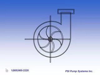
Problem Statement The problem is the ability of a record player to keep a specific speed. The synchronous motor used on a record player is supposed to play the record at a specific speed. However, the motor does not always run at the specified speed which causes the record to sound out of pitch. A precision variable frequency drive will provide a constant frequency to the synchronous motor which in turn will maintain a constant speed of the record table.
Executive Summary Synchronous motors are motors that run at a specific speed. A customer may want to run the motor at different speeds, like for a record player that needs to operate at 45 and 33 1/3 rpm. A precision variable frequency drive is a way to speed up or slow down the motor by changing the frequency of the input voltage. This product will be designed to adjust the frequency between 58 to 62 hertz by the turning of a dial. The digital display will be accurate up to the thousandth of a hertz. In addition, a strobe light will allow the user to observe the rpm of the motor. The precision variable frequency drive will have a long term drift that requires a gradual decrease/increase of speed that allows for more accurate tuning.
Operating Environment • Indoors • No extreme dust • No extreme temperatures
Intended Users and Uses • Users • Avid music listener • Lay person • Uses • Adjust the frequency of the turn-table • With other synchronous motors
Assumptions • Constant linkage – the belt connecting the motor to the turntable is constant over a short time period. Basically, an increase in motor speed by a certain factor will result in an increase in the speed of the turntable by the same factor. • Plug – the plug from the record player can plug into a standard three pronged outlet.
Limitations • Precision – the precision variable frequency drive will be accurate to .1 Hertz. • Price – the total end product cost must be less than $1,000. • Frequency Range – 58 to 62 Hertz with step of 0.1 Hertz. • Nominal Voltage – 120 VAC. • Stability – the precision variable frequency drive must be stable. Short term stability of less that +/- 0.01%. It shall not be affected by fluctuations in incoming voltage or frequency. • Power Output – 75 W minimum. • Input Voltage – the input voltage will be a standard household outlet of 120 V at 60 Hz. single phase
Design Considerations • Maximum weight and size • Minimum power output • Minimum operating frequency
Functional Requirements • Synchronous motor frequency controller • Knob controller to adjust frequency • Digital read-out of frequency • Portable strobe system
Technology Considerations • Pulse Width Modulation • Crystal Oscillator
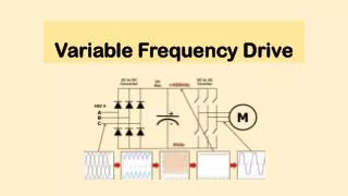
Technology Approach Considerations • An AC/DC converter was needed to change the input of AC voltage to DC voltage. • The pulse width modulator will allow the user to change the frequency of the voltage. 3. A low pass filter would change the DC signal back into an AC signal at the desired frequency. 4. A amplifier would be needed to step the voltage up to an appropriate level to feed the turn-table. 5. A frequency counter would be used to display the frequency output of the low pass filter. 6. A strobe light system would be used to measure the RPM of the motor.
Testing Considerations • Pulse-width modulator • Strobe system • Complete system
Power Source 110-120 VAC 60 Hz nominal frequency Standard wall outlet
AC to DC Converter The AC to DC converter will take in 120 VAC and produce 25 Volt DC. The project team will purchase this component. The group is going to purchase a converter of the same type that a cell phone charger would use. The converter is around $20 to purchase. After the power has been changed into DC pulse width modulation can take place.
Frequency Counter A frequency counter will connect to the circuit after the low pass filter and measure the frequency of the AC signal being outputted to the voltage amplifier. This device will display the frequency of the power it is sampling on a LCD screen. Figure 8 shows a picture of the frequency counter that will be purchased.
Figure 10: Strobe Light Schematic (Vinyl Engine) Figure 11: The strobe light shinning on the special disc. (Vinyl Engine) Strobe Light System The strobe system will be used to measure the the RPM of the turn-table. As the picture shows, there are three different circles for the three rates, 33 1/3, 45, and 78.
Summary Upon review of the detailed project design, it has been decided to continue the project as planned. It will be continued as scheduled because the detailed design has meet the functional requirements of the precision variable frequency drive.