Download
1 / 18
200 likes | 299 Vues
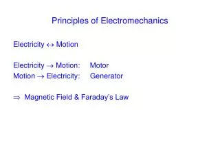
Dive into the core concepts of electromagnetics, Maxwell's equations, rotational motion, and the magnetic field. Explore Newton's laws, torque, power, magnetic circuits, and Faraday's law. Unravel the principles underlying electromagnetic and electromechanical systems.

E N D
1. Maxwell Equations Gauss(D) Gauss (B) Ampere Faraday
2. Rotational motion, Newton’s law Majority of electric machines rotate about an axis called a shaft of the machine. 2.1. Angular position - an angle at which the object is oriented with respect to an arbitrary reference point. 2.2. Angular velocity (speed) - a rate of change of the angular position. (2.8.1) m – angular velocity in radians per second fm – angular velocity in revolutions per second nm – angular velocity in revolutions per minute (2.8.2) (2.8.3)
2. Rotational motion, Newton’s law 2.3. Angular acceleration - a rate of change of angular velocity. (2.9.1) 2.4. Torque (moment) - a “rotating force”. axis (2.9.2) Here F is an acting force, r is the vector pointing from the axis of rotation to the point where the force is applied, is the angle between two vectors. r F Newton’s law of rotation: (2.9.3) J is a moment of inertia (a mass equivalent).
2. Rotational motion, Newton’s law 2.5. Work W – amount of energy transferred by a force. (2.10.1) If the torque is constant: (2.10.2) 2.6. Power P – increase in work per unit time. (2.10.3) For a constant torque: (2.10.4)
3. The magnetic field Basic principles underlying usage of magnetic field • A wire caring a current produces a magnetic field around it. • A time-changing magnetic field induces a voltage in a coil of wire if it passes through that coil (transformer action). • A wire caring a current in the presence of a magnetic field experiences a force induced on it (motor action). • A wire moving in a presence of a magnetic field gets a voltage induced in it (generator action).
3. The magnetic field 3.1. Production of magnetic field The Ampere’s law: (2.12.1) Where H [A-turns/m] is the intensity of the magnetic field produced by the current Inet For the ferromagnetic cores, almost all the magnetic field produced by the current remains inside the core, therefore the integration path would be lc and the current passes it N times. (2.12.2)
3. The magnetic field Magnetic flux density: (2.13.1) where is the magnetic permeability of a material. r – the relative permeability The total flux in a given area: (2.13.2) If the magnetic flux density vector B is perpendicular to a plane of the area: (2.13.3)
3. The magnetic field 3.2. Magnetic circuits Similarly to electric circuits, there are magnetic circuits … Instead of electromotive force (voltage) magnetomotive force (mmf) is what drives magnetic circuits. (2.14.1) Direction of mmf is determined by RHR… Like the Ohm’s law, the Hopkinson’s Law: (2.14.2)
Permeance: Magnetic flux: Therefore, the reluctance: Serial connection: Parallel connection: 3. The magnetic field (2.15.1) (2.15.2) (2.15.3) (2.15.4) (2.15.5)
3. The magnetic field 3.3. Magnetic behavior of ferromagnetic materials Magnetic permeability can be defined as: (2.23.1) and was previously assumed as constant. However, for the ferromagnetic materials (for which permeability can be up to 6000 times the permeability of air), permeability is not a constant… A saturation (magnetization) curve for a DC source
3. The magnetic field The magnetizing intensity is: (2.24.1) The magnetic flux density: (2.24.2) Therefore, the magnetizing intensity is directly proportional to mmf and the magnetic flux density is directly proportional to magnetic flux for any magnetic core. Ferromagnetic materials are essential since they allow to produce much more flux for the given mmf than when air is used.
3. The magnetic field 3.4. Energy losses in a ferromagnetic core If instead of a DC, a sinusoidal current is applied to a magnetic core, a hysteresis loop will be observed… If a large mmf is applied to a core and then removed, the flux in a core does not go to zero! A magnetic field (or flux), called the residual field (or flux), will be left in the material. To force the flux to zero, an amount of mmg (coercive mmf) is needed.
4. The Faradays law If a flux passes through a turn of a coil of wire, a voltage will be induced in that turn that is directly proportional to the rate of change in the flux with respect to time: (2.28.1) Or, for a coil having N turns: (2.28.2) eind – voltage induced in the coil N – number of turns of wire in the coil - magnetic flux passing through the coil
4. The Faradays law The “minus” sign in the equation is a consequence of the Lentz’s law stating that the direction of the voltage buildup in the coil is such that if the coil terminals were short circuited, it would produce a current that would cause a flux opposing the original flux change. If the initial flux is increasing, the voltage buildup in the coil will tend to establish a flux that will oppose the increase. Therefore, a current will flow as indicated and the polarity of the induced voltage can be determined. The minus sign is frequently omitted since the polarity is easy to figure out.
4. The Faradays law The equation (2.28.2) assumes that the same flux is passing through each turn of the coil. If the windings are closely coupled, this assumption almost holds. In most cases, a flux leakage occurs. Therefore, more accurately: (2.30.1) (2.30.2) (2.30.3) - a flux linkage of the coil: (2.30.4)
5. Production of induced force on a wire A second major effect of a magnetic field is that it induces a force on a wire caring a current within the field. (2.32.1) Where I is a vector of current, B is the magnetic flux density vector. For a wire of length l caring a current i in a magnetic field with a flux density B that makes an angle to the wire, the magnitude of the force is: (2.32.2) This is a basis for a motor action.
6. Induced voltage on a conductor moving in a magnetic field The third way in which a magnetic field interacts with its surrounding is by an induction of voltage in the wire with the proper orientation moving through a magnetic field. (2.33.1) Where v is the velocity of the wire, l is its length in the magnetic field, B – the magnetic flux density This is a basis for a generator action.