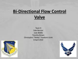
Bi-Directional Flow Control Valve
Bi-Directional Flow Control Valve. Team 9 Dale Bernier Judy Biddle Timothy Brown Christopher "Robby" Freeborn-Scott 8 April 2010. Brief Overview. Background Problem/Objective Design Selection Specifications/Cost Calculations Manufacturing Testing. Introduction & Background.

Bi-Directional Flow Control Valve
E N D
Presentation Transcript
Bi-Directional Flow Control Valve Team 9 Dale Bernier Judy Biddle Timothy Brown Christopher "Robby" Freeborn-Scott 8 April 2010
Brief Overview • Background • Problem/Objective • Design Selection • Specifications/Cost • Calculations • Manufacturing • Testing
Introduction & Background September 11, 2001 Pentagon Attack http://upload.wikimedia.org
Wet Pipe Sprinkler System Hangers Cross Main Riser Waterflow Alarm Branch Lines Check Valve Automatic Sprinkler Heads Fire Department Connection Alarm Valve Post Indicator Valve Main Control Valve Main Drain Inspector’s Test Valve Distribution Main
Problem • Currently, only one-directional mechanical flow valves are available on the market
Objective Design and prototype a purely mechanical bi-directional flow control valve
Single Riser Schematic Fire Area -only the sprinkler heads affected by the fire will activate Riser
Double Riser Schematic Valve to be installed in a looped sprinkler system. Riser Riser
Bi-Directional Flow Control Valve Schematic Sprinkler Head Bi-Directional Flow Control Valve Spacing of control valve determined by sprinkler system designer
Design Concepts 5 Design concepts originally developed Chosen Design
Assumptions • Gravitational effect neglected • Spring constants same • Initial velocity is zero
Calculations Sample Calculation for Required Spring Constants the spring rate required for 60 gpm flow Also solved for 70, 80, 90, & 100 gpm
Free Body Diagram Valve Open
Free Body Diagram Valve Pressures
CFD Modeling Computational Fluid Dynamics www.comsol.com
Cost Analysis Total Spent on parts: $290.77
Parts Ordered E-Clips O Rings Shafts/casing Springs Rubber
Cost Analysis Original Parts Cost Estimate: $141.70 Initial Purchase Parts Actual Cost: $165.73 Additional Parts Ordered: $125.04 Total Cost: $290.77 Budget: $1000.00 - $290.77 (Parts Ordered) - $250.00 (Machining Cost)Budget Remaining: $459.23 Does not include testing apparatus (fire pump, flow meters, and valves)
Cost Benefit • Sprinkler system cost between $1-5 million • With valve: $2000-$10,000 additional cost to sprinkler system installation • Without bi-directional flow control valve • Same protection is to install duplicate system
Machining • Shaft-Holders machined using Water Jet
CNC LatheComputer Numerical Controlled • Specialized machining done by others www.sj-mc.com
Testing Apparatus Test water supplied by Fire Hydrant CU’s used to quickly flip the flow fuse GV1 used to throttle the system BV – Ball Valve FM – Flow Meter PI – Pressure Gage CU – Union GV – Gate Valve test room location Fire Hydrant 100gpm. 110psi PI PI 2 1 3” hose 1 ¾ ” hose Test Valve BV 1 FM 1 CU 1 CU 2 GV 1 Fire Department Gate Valve Materials for test apparatus supplied by sponsor
Testing Results • Several test sessions conducted • Valve is working • however not at desired flow rates • Pressure drop found to be 20 psi at 39 gpm • Shaft holder broke • Remanufactured out of stainless steel • Stronger springs ordered • Additional testing planned
Conclusion Discussed: • Background • Problem/Objective • Design Concept • Cost/Budget • Calculations • Testing
Special Thanks • Dr. Steven Van Sciver • Dr. Daudi Waryoba • Mr. Vaughn Williams • Mr. Keith Larson • Cody Epperson • Tallahassee Fire Training Center
References • McMaster.com • Fundamentals of Thermal-Fluid Science (3rd edition). By Robert Rizza, Prentice Hall, Inc., 2004 • http://upload.wikimedia.org/wikipedia/commons/d/d2/The_Pentagon_US_Department_of_Defense_building.jpg • www.comsol.com • www.sj-mc.com