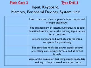
Peripheral Devices
Peripheral Devices. Computer Architecture CS 215. Overview. Magnetic disk drives: ubiquitous and complex Other moving media devices: tape and CD ROM Display devices Video monitors: analog characteristics Video terminals Memory mapped video displays Flat panel displays

Peripheral Devices
E N D
Presentation Transcript
Peripheral Devices Computer ArchitectureCS 215
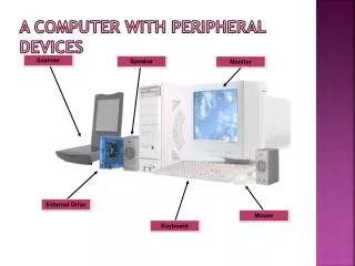
Overview • Magnetic disk drives: ubiquitous and complex • Other moving media devices: tape and CD ROM • Display devices • Video monitors: analog characteristics • Video terminals • Memory mapped video displays • Flat panel displays • Printers: dot matrix, laser, inkjet • Manual input: keyboards and mice • A to D and D to A converters: the analog world
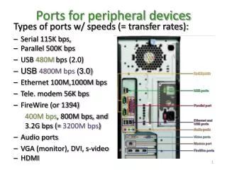
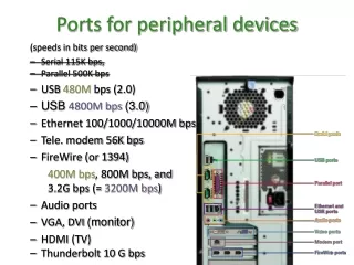
Some Common Peripheral Interface Standards Bus StandardData RateBus Width Centronics ~50KB/s 8-bit parallel EIA RS232/422 30-20K B/s bit-serial SCSI 10-500 MB/s 16-bit parallel Ethernet 10-1000 Mb/s bit-serial USB 1.5-12 Mb/s bit-serial USB-2 480 Mb/s bit-serial FireWire† 100-400 Mb/s bit-serial FireWire-800† 800 Mb/s bit-serial †Also known as Sony iLink, or IEEE1394 and 1394b, respectively
Disk Drives—Moving Media Magnetic Recording • High density and non-volatile • Densities approaching semiconductor RAM on an inexpensive medium • No power required to retain stored information • Motion of medium supplies power for sensing • More random access than tape: direct access • Different platters selected electronically • Track on platter selected by head movement • Cyclic sequential access to data on a track • Structured address of data on disk • Drive: Platter: Track: Sector: Byte
Simplified View of Disk Track and Sector Organization • An integral number of sectors are recorded around a track • A sector is the unit of data transfer to or from the disk
Simplified View of Individual Bits Encoded on a Disk Track • Inside tracks are shorter & thus have higher densities or fewer words • All sectors contain the same number of bytes • Inner portions of a platter may have fewer sectors per track • Small areas of the disk are magnetized in different directions • Change in magnetization direction is what is detected on read
Typical Hard Disk Sector Organization • Serial bit stream has header, data, & error code • Header synchronizes sector read and records sector address • Data length is usually power of 2 bytes • Error detection/correction code needed at end
Disk Formatting • Disks are pre-formatted with track and sector address written in headers • Disk surface defects may cause some sectors to be marked unusable for the software
The PC AT Block Address for Disk Access • Head number determines platter surface • Cylinder is track number for all heads • Count sectors, up to a full track, can be accessed in one operation
The Disk Access Process 1. OS Communicates LBA to the disk interface, and issues a READ command. 2. Drive seeks to the correct track by moving heads to correct position, and enabling the appropriate head. 3. Sector data and ECC stream into buffer. ECC is done "on the fly." 4. When correct sector is found data is streamed into a buffer. 5. Drive communicates "data ready" to the OS 6. OS reads data byte by byte or by using DMA.
Static Disk Characteristics • Areal density of bits on surface density = 1/(bit spacing track spacing) • Maximum density: density on innermost track • Unformatted capacity: includes header and error control bits • Formatted capacity: bytes sectors tracks capacity = # of surfaces sector track surface
Dynamic Disk Characteristics • Seek time: time to move heads to cylinder • Track-to-track access: time to adjacent track • Rotational latency: time for correct sector to come under read/write head • Average access time: seek time + rotational latency • Burst rate (maximum transfer bandwidth) revs sectors bytes burst rate = sec rev sector
Video Monitors • Color or black and white • Image is traced on screen a line at a time in a raster format • Screen dots, or pixels, are sent serially to the scanning electron beam • Beam is deflected horizontally & vertically to form the raster • About 60 full frames are displayed per second • Vertical resolution is # of lines: ≈500 • Horiz. resolution is dots per line: ≈700 • Dots per sec. ≈ 60500700 ≈ 21M
Two Video Display Types: Terminal & Memory Mapped • Video monitor can be packaged with display memory and keyboard to form a terminal • Video monitor can be driven from display memory that is memory mapped • Video display terminals are usually character oriented devices • Low bandwidth connection to the computer • Memory mapped displays can show pictures and motion • High bandwidth connection to memory bus allows fast changes
The Video Display Terminal (Character-oriented, not often seen)
Memory Mapped Video Display (Pixel-oriented)
Memory Representations of Displayed Information • Bit mapped displays • Each pixel represented by a memory datum • Black & white displays can use a bit per pixel • Gray scale or color needs several bits per pixel • Character oriented (alphanumeric) displays • Only character codes stored in memory • Character code converted to pixels by a character ROM • A character generates several successive pixels on several successive lines
Character ROM for 57 Character in a 79 Field • Bits of a line are read out serially • Accessed 9 times at same horizontal position and successive vertical positions
Video Controller for an Alphanumeric Display • Counters count the 7 dots in a char., • the 80 characters across a screen, • the 9 lines in a character, and • the 67 rows of characters from top to bottom
Memory-Mapped Video Controller for a 24-bit Color Display • Memory must store 24 bits per pixel for 256 level resolution • At 20M dots per sec. the memory bandwidth is very high • Place for video RAM
Flat Panel Displays • Allow electrical control over the transparency of a liquid crystal material sandwiched between glass plates, dot by dot • 3 dots per pixel for color, one for black&white • Dots are scanned in a raster format, so controller similar to that for video monitor • Passive matrix has X & Y drive transistors at edges • Active matrix has one (or 3) transistor per dot
Printers—Ways of Getting Ink on Paper • Dot matrix printer: • Row of solenoid actuated pins, could be height of char. matrix • Inked ribbon struck by pin to mark paper • Low resolution • Laser printer: • Positively charged drum scanned by laser to discharge individual pixels • Ink adheres to remaining positive surface portions • 300 to 1200 dots per inch resolution • Ink-jet printers: • Ultrasonic transducer squirts very small jet of ink at correct pixels as head moves across paper • Intermediate between the 2 in price and resolution
Character Generation in Dot Matrix Printers • Can print a column at a time from a character ROM • ROM is read out parallel by column instead of serial by row, as in alphanumeric video displays
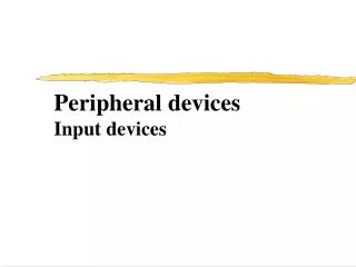
Manual Input Input Devices—Keyboards and Mice • Very slow input rates • 10 characters of 8 bits per sec. on keyboard • Mouse tracking somewhat faster: few X & Y position change bits per millisecond • Mouse click: bit per 1/10 second • Main thrust in manual input design is to reduce number of moving parts
ADC and DAC Interfaces • Begin and Done synchronize A to D conversion, which can take several clock cycles • D to A conversion is usually fast in comparison
R-2R Ladder DAC—Voltage Out Proportional to Binary Number x 1 1 1 V0 = ( xn-1 + xn-2 + xn-3 + + x0 ) kVR 2 4 2n-1
Counting Analog-to-Digital Converter • Counter increments until DAC output becomes just greater than unknown input • Conversion time 2n for an n-bit converter
Successive-Approximation ADC • Successive approximation logic uses binary chopping method to get n bit result in n steps
Successive Approximation Search Tree • Each trial determines one bit of result • Trial also determines next comparison level • For specific input, one path from root to leaf in binary tree is traced • Conversion time nfor an n-bit converter
Errors in ADC and DAC • Full scale error: voltage produced by all 1’s input in DAC or voltage producing all 1’s in ADC • Offset error: DAC output voltage with all 0’s input • Missing codes: digital values that are never produced by an ADC (skips over as voltage increased) • Lack of monotonicity:DAC monotonicity means voltage always increases as value increases • Quantization error: always present in DAC or ADC as a theoretical result of conversion process
Signal Quantization and Quantization Error in an ADC • Ideal output of the ADC for a linearly increasing input • Error signal corresponding to the ideal ADC output Quantization error = ±Vf/2n+1