Download
1 / 67
670 likes | 779 Vues
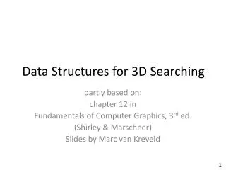
CS246 Data & File Structures Secondary Memory. Instructor: Li Ma Office: NBC 126 Phone: (713) 313-7028 Email: malx@tsu.edu Webpage: http://itscience.tsu.edu/ma Department of Computer Science Texas Southern University, Houston. January, 2007. Memory Types.

E N D
CS246 Data & File StructuresSecondary Memory Instructor: Li Ma Office: NBC 126 Phone: (713) 313-7028 Email: malx@tsu.edu Webpage: http://itscience.tsu.edu/ma Department of Computer Science Texas Southern University, Houston January, 2007
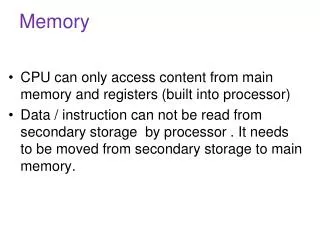
Memory Types • Cache: RAM technology Capacity 256K- 1 M, 10 nanoseconds • Main memory: RAM - ROM technology 100 M- 1G, 100 nanoseconds • Secondary storage (Disk): 10 G-1000 G, 10-30 milliseconds • Tertiary Storage (Tape, CD):1G -100 T, a few seconds- a few minutes by Li Ma, TSU - cs344
cache Memory Main Memory Disk Memory Tape Memory CPU Memory Hierarchy Components towards the left side, which are nearer of the CPU, need faster access times and thus are more expensive. Components on the right side provide slower access times, but cost less. Information must flow back and forth in the hierarchy by Li Ma, TSU - cs344
Magnetic Disks • Bits of data (0’s and 1’s) are stored on circular magnetic platters called disks • A disk rotates rapidly • A disk head reads and writes bits of data as they pass under the head • Often several platters are organized into a disk pack by Li Ma, TSU - cs344
Magnetic Disks (cont) • Disks are non-volatile, stable • They have tremendous capacity (about 1000 times more than RAM) • Much cheaper than RAM (40 times cheaper per Meg) by Li Ma, TSU - cs344
Disk Organization • Disks are direct access storage devices • A disk is composed of a disk assembly and a head assembly • A disk assembly is a collection of one or more platters with a common spindle (axle) • A head assembly consists of several disk arms ending in disk heads • The arm can move outwards or inwards towards the spindle • Information is stored in the surface of the platters by Li Ma, TSU - cs344
read/write head (1 per surface) Surface 1 Surface 2 Surface 3 moving arm (starts and stops) Surface 4 Surface 5 Surface 6 spindle (rotating shaft never stops) Disk with 3 Platters by Li Ma, TSU - cs344
Track Sector (wedge) Block (sequence of bits) A Surface of A Disk by Li Ma, TSU - cs344
A Surface of A Disk (cont) • Each platter has two surfaces to put data • Each surface is divided into tracks (concentric circles) • Tracks directly above and below one another form a cylinder • Each track is divided into sectors • A sector is the smallest addressable unit by Li Ma, TSU - cs344
Data on Surface • Each block of data is addressed by its track, sector, and surface • e.g. track 126, sector 4, surface 3 • Given the address of a block, the disk head moves to the given track, and waits for the block to rotate into position by Li Ma, TSU - cs344
Data on Surface (cont) • It takes a long time for the disk head to move to the given track • But once in position, the block rotates under past the head very quickly • Consequently, it takes a long time to read the first bit in a block, but very little time to read the remaining bits in the block by Li Ma, TSU - cs344
Data on Surface (cont) • For this reason, a disk reads/writes an entire block of data at a time, not just a single bit or byte • Typically, only one head can read/write at a given time. All heads move together, they are all at the same radius by Li Ma, TSU - cs344
Cylinders • The set of tracks at a given radius of a disk pack • The set of tracks that can be accessed without moving the disk arm • Moving the disk arm is relatively slow • Once the heads are positioned at a cylinder, data in that cylinder can be accessed more quickly than data in other cylinders • We try to store related data (e.g. a file) on the same cylinder by Li Ma, TSU - cs344
Disk Capacity • The number of cylinders is the same as the number of tracks on the single surface • Total capacity is (# of cylinders)*(cylinder capacity) – drive capacity • Cylinder capacity is (# of tracks per cylinder)*(track capacity) • Track capacity is (# of sectors per track)*(bytes per sector) by Li Ma, TSU - cs344
Disk Capacity (cont) • The amount of data on a track and the number of tracks on a surface give the density of the medium • Disks usually have 5 to 15 platters (10 to 30 surfaces) • Track may have as many as 50 sectors • A sector holds from 512B to 4KB data • This has improved consistently and still will by Li Ma, TSU - cs344
Disk Capacity (cont) • Tracks used to have the same capacity (NOTE: some tracks are physically bigger than others) • This schema keeps things simple at the cost of same waste (given by differences in density) • In modern disks, outer tracks store more sectors than inner tracks • Look at Table 3.1 of your textbook (page 49) by Li Ma, TSU - cs344
Disk Input/Output • The disk controller takes care of disk I/O • It controls one or more disk drives • To read from a disk, the controller must determine the platter, track, and sector of the block to be read • The same for writing by Li Ma, TSU - cs344
Disk Input/Output (cont) • Then the arm is moved to be positioned under the right track – seeking • The disk is allowed to rotate so the right sector is under the head – latency • The block is read when directly under the head, and its contents go to a buffer in the disk controller – transfer • Then the buffer contents are sent to the RAM by Li Ma, TSU - cs344
Disk Input/Output (cont) • Time for disk access is the sum of seek time, latency time, and transfer time • Seeking is the most expensive part since it is mechanical in nature, it varies considerably • Average seek time is about traversing 1/3 of the total number of cylinders • Most disks today have average seek time of less than 10 ms by Li Ma, TSU - cs344
Disk Input/Output (cont) • Latency time depends on how far the sector is from the head and how fast the disk rotates • On average, the latency time is half a revolution • Most disks today rotate at least at 5000 – 9000 rpm (11 – 6 ms per revolution, floppy disks are much slower) by Li Ma, TSU - cs344
Disk Input/Output (cont) • Transfer time is calculated as follows • Transfer time for a 4KB block is about half a millisecond • Time taken by disk controller processing is negligible by Li Ma, TSU - cs344
Organizing Data on Disks • Files are a collection of blocks/pages • How information is placed on sectors affects performance greatly • Obvious solution: place data in adjacent sectors • Head may not be able to read adjacent sectors • Alternative solution: interleaving of sectors • Interleaving factor: number of sectors that must separate two logically adjacent sectors by Li Ma, TSU - cs344
Organizing Data on Disks (cont) • Nowadays some disks can read physically adjacent sectors • Cluster: fixed number of adjacent sectors, all treated as an I/O unit • Seek time and latency time are amortized when reading clusters by Li Ma, TSU - cs344
Organizing Data on Disks (cont) • Extents: group of adjacent clusters, not necessarily fixed size • Large amount of data can be read efficiently if in the same extent • However, as data grows an extent may not be able to grow • If possible, files are organized into extents by Li Ma, TSU - cs344
Organizing Data on Disks (cont) • Another possible approach: put related data in the same cylinder • If several cylinders needed, use adjacent cylinders • Seek time is limited to one average seek time for all data – at most we have to move to adjacent cylinder • Latency is non-existent if we need to read all tracks by Li Ma, TSU - cs344
Organizing Data on Disks (cont) • Another technique: use multiple disks • If n disks associated with the same disk controller, data can be read to/write from all n disks independently and in parallel • Seek time and latency time go down by a factor of n • But, will all n disks be busy all the time? by Li Ma, TSU - cs344
Organizing Data on Disks (cont) • Disks are slow but cheap, so some techniques for improving I/O rely on having several disks (say, n) available • Disk stripping: split a file into several drives • Write each piece of the file to the same track of each disk • I/O proceeds in parallel • Reassembly the block in the cache of the disk controller • Read/write is now n times faster by Li Ma, TSU - cs344
Organizing Data on Disks (cont) • Other ways to speed up reading: • By using the disk whose head is closer to the sector we want • By keeping all disks busy regardless of which order we need to access the data by Li Ma, TSU - cs344
Organizing Data on Disks (cont) • Fragmentation • Internal fragmentation: caused by mismatch between size of sectors and size of logical units (records, pages) that a file uses • Records can span sectors or leave space unused • Same problem arises with cluster, especially when clusters are larger by Li Ma, TSU - cs344
Organizing Data on Disks (cont) • Fragmentation • External fragmentation: the inability to give additional adjacent space to a growing file • The data for the files is dispersed in physically separated extents/clusters/sectors • Seek and latency time to scan the file sequentially go up by Li Ma, TSU - cs344
Disk Scheduling • Request for read/write accumulate in a queue in the disk controller • When no requirement exists on the order to read/write, letting the disk controller choose the order improves throughput by Li Ma, TSU - cs344
Disk Scheduling – Elevator Algorithm • Scan the disk by moving the arm all the way in and out, and back again (like an elevator) • As heads pass over a cylinder, they stop if there are read/write requests involving that cylinder • When the heads have no request ahead of them, they reverse directions by Li Ma, TSU - cs344
Disk Scheduling – Elevator Algorithm (cont) • Advantages • very simple algorithm, pretty good on average • Disadvantages • works better when there are plenty of requests known in advance (in queue) • still sensitive to arrival times and order by Li Ma, TSU - cs344
Pre-fetching & Disk Buffering • In some applications, we can predict that certain sectors will need to be read in the near future • So we can go ahead and schedule to read them before a request arrives • This allows the elevator algorithm to use the information, helping improve scheduling by Li Ma, TSU - cs344
Pre-fetching & Disk Buffering (cont) • Data is transferred from the head to the buffer (memory) in the disk controller • Modern disk controllers have larger and larger buffers • When a request is received, the disk controller checks first its buffer to see if the sector is already there by Li Ma, TSU - cs344
Pre-fetching & Disk Buffering (cont) • If so, we are saving all disks I/O. Thus, large buffers improve performance tremendously • This buffer is treated like a cache • The same idea is applied for writing, by delaying writings until we can do several writings together by Li Ma, TSU - cs344
Disk Failures • Intermittent Failures: we fail to read or write but succeed after repeated tries • Media Decay: We cannot read a sector correctly regardless of how many times we try • Write Failure: We cannot write a sector successfully and we cannot read the sector afterwards • Disk Crash: Entire disk become unreadable, because of a big failure, like a head crash • Mean time to failure: time by which 50% of a population of disks will have failed catastrophically. The average time may be 10 years or more by Li Ma, TSU - cs344
Correction of Failures • Checksum • When reading, head returns data and a status (successful or unsuccessful) • Checksum is additional bits for each sector, its value depends on the value of the data in the sector • When data is read, the checksum for the sector is read, too • The checksum can be calculated from the data and compared to the stored value by Li Ma, TSU - cs344
Correction of Failures (cont) • Checksum • The larger the checksums, the smaller the chance that bad data bits have the same checksum as good ones • Simple checksum: parity counts • Even parity count: the number of 1’s in data and parity is always even – only for single error • Many schemes use several parity bits, not just one (say, n bits); chances of an error going undetected are 1/2n • These techniques help if we can read, but if we can’t read, we still have a problem by Li Ma, TSU - cs344
Correction of Failures (cont) • Stable storage • Two copies are made of every sector: X1 and X2 • When writing, we write to X1 and then check the written copy • Failure occurs if check is not successful until a pre-determined number of tries is reached => media failure • Then repeat the process for X2 • To read, read X1 and check the status • If bad status, repeat the read until successful or number of tries reached. • If failure, repeat the read with X2 by Li Ma, TSU - cs344
Correction of Failures (cont) • Stable storage • This technique relies on the fact that media failure for both X1 and X2 is very small • This schema can be implemented in one or several disks • The larger the number of backup disks, the lower the risk of failure by Li Ma, TSU - cs344
Correction of Failures (cont) • RAID: Redundant Array of Independent Disks • Data is stored in some disks (called data disks) and mirrored in other disks (called redundant disks) • RAID level 1: simply mirror the data • This approach doubles the number of disks • RAID Level 4: only use one redundant disk • Assume all disks are identical • Number all sectors on each from 1 to n • In the redundant disk, store in the ith sector the parity bits for the ith sectors of all n disks by Li Ma, TSU - cs344
Correction of Failures (cont) • RAID: Redundant Array of Independent Disks • Reading in this schema does not involve reading the redundant disk (nothing out of order involved) • Writing involved changing the corresponding parity sector in the redundant disk • This can be done by comparing the new and old content of the sector to be written • By taking the sum mod 2 can be determined which bits need to be changed in the parity sum (1’s indicate need for change, 0’s indicate no need) • This schema involves 4 disk I/Os to write one sector by Li Ma, TSU - cs344
Correction of Failures (cont) • RAID: Redundant Array of Independent Disks • When a disk crashes, we do the following: • If the bad disk is the redundant disk, replace it with a new one and re-compute the parity bits • If the bad disk is a data disk, replace it with a new one and re-compute the data from another disk; To do so, simply add all other data disk and parity disk mod 2 by Li Ma, TSU - cs344
Correction of Failures (cont) • RAID: Redundant Array of Independent Disks • The previous schema presents a bottleneck in that the write to any disk represents a write to the redundant disk • For n data disks, the redundant disk has n times of writes • In order to improve on this, we use RAID level 5 • Treat all disks as data and redundant (spread the redundant sectors among all disks) • One can assign certain sectors (blocks, cylinders) of each disk to be redundant for other disks by Li Ma, TSU - cs344
Correction of Failures (cont) • RAID: Redundant Array of Independent Disks • RAID level 5 • If there are n+1 disks numbered 0,.., n, we can put redundant data in cylinder i of disk j if n+1 divided by i has j as remainder (round robin effect) • Example: if n = 3, disks are 0,1,2,3. Disk 0 is redundant for cylinders 4, 8, 12,…; disk 1 is redundant for cylinders 1, 5, 9,…; disk 2 is redundant for cylinders 2, 6, 10,…; and disk 3 is redundant for cylinders 3, 7, 11,… • Each disk has the same read and write load on average by Li Ma, TSU - cs344
Correction of Failures (cont) • RAID: Redundant Array of Independent Disks • Not one of the above solves the problem of multiple disk crashes, but RAID level 6 can do it • RAID level 6: use self correcting codes (Huffman codes) to determine where to write by Li Ma, TSU - cs344
Summary for Disk • Memory Hierarchy • Disk Organization • Data on Surface • Disk Capacity • Disk Input/Output • Organization of Data on Disks • Disk Scheduling • Disk Failure and Correction by Li Ma, TSU - cs344
Magnetic Tape • A sequence of bits (1’s and 0’s) is stored on magnetic tape • For storage, the tape is wound on a reel • To access the data, the tape is unwound from one reel to another • As the tape passes the head, bits of data are read from or written onto the tape by Li Ma, TSU - cs344
reel 1 reel 2 tape read/write head Magnetic Tape (cont) by Li Ma, TSU - cs344