IOTs for ESS
IOTs for ESS. Morten Jensen. www.europeanspallationsource.se November 12, 2013. EnEfficient RF Sources Workshop Cockcroft Institute 3-4 June 2014. Agenda. Introduction to ESS Power profile and Technology Choices IOTs fo r ESS Review of accelerator experience with IOTs


IOTs for ESS
E N D
Presentation Transcript
IOTs for ESS Morten Jensen www.europeanspallationsource.se November 12, 2013 EnEfficient RF Sources Workshop Cockcroft Institute 3-4 June 2014
Agenda • Introduction to ESS • Power profile and Technology Choices • IOTs for ESS • Review of accelerator experience with IOTs • The ESS IOT specification • Current status Experiments Target Linear accelerator
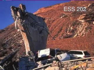
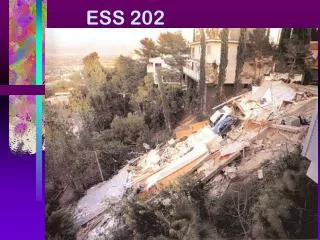
Overview • The European Spallation Source (ESS) will house the most powerful proton linac ever built. • The average beam power is five times greater than SNS. • The peak beam power will be over seven times greater than SNS • The linac will require over 150 individual high power RF sources • We expect to spend over 200 M€ on the RF system alone
NeutronSpallation Sources Short Pulse Concept Long Pulse Concept • Protons stored in circular accumulator • Accumulator ring of 300 m = 1 μs • Neutrons cooled in moderator following impact on target • Neutron time constant = few 100 μs • Short pulse at ESS power would destroy target or a 100 μs ring would be around 30 km • No accumulator • Neutrons still cooled in moderator following impact on target • Choppers and long beam lines provide energy measurement • Peak beam power ≤ 125 MW Proton Pulse Neutron Output
TheEuropean Spallation Source • ESS is a • long-pulse neutron spallation source based on a large linac • Proton linac designed for 5 MW average power • European project located in the southern part of Sweden
The ESS Superconducting Power Profile > 150 cavities/couplers 84 High Beta 704 MHz (5 cell) 1.2 MW IOT 1.5 MW Klystron as backup 26 Spoke Cavities 352 MHz 2*200 kW Tetrodes 36 Medium Beta 704 MHz (6 cell) 1.5 MW Klystrons Power splitting under consideration 1 RFQ and 5 DTL tanks 352 MHz 2.8 MW Klystrons 125 MW peak (4% duty) 5 MW average
Elliptical (704 MHz) RF System Layout Klystrons Modulator Racks and Controls WR1150 Distribution 4.5 Cells of 8 klystrons for Medium Beta 10,5 Cells of 8 klystrons (IOTs) for High Beta
Where next? The ESS Requirement Carbon Neutral Innovative Green Time to develop Super Power IOT ** Plus overhead for control
The Inductive Output Tube • Invented in 1938 by Andrew V. Haeff as a source for radar • To overcome limitation of output power by grid interception • Pass beam trough a resonant cavity • Achieved: 100 W at 450 MHz, 35% efficiency • Used first in 1939 to transmit television images from the Empire State Building to the New York World Fair • IOTs then lay dormant • Intense competition with velocity modulated tubes (klystron had just been invented by the Varian Brothers.) • Difficult to manufacture • The IOT is often described as a cross between a klystron and a triode hence Eimac’s trade name ‘Klystrode’
How does the IOT work? Control Deceleration = RF Output Acceleration Source Beam IOT (Density modulated) Reduced velocity spread compared to klystrons Higher efficiency No pulsed high voltage Magnetic field RF input Biased Control Grid RF output
A Questionnaire (This will take one minute of your time and will help us to improve our service to you!) Who here believes that high efficiency is a good thing? Do we really need overhead for LLRF? Do we like to operate below absolute maximum output power to improve reliability? Is the efficiency at saturation really the most important measure? Need to consider the whole system and the actual point of operation
IOT’s don’t saturate. Built-in headroom for feedback. Back-off for feedback hsat ~ 65-68% • ESS ~ 45% • ~ 70% The Performance Comparison IOT MB-IOT Klystron/MBK +6 dB Short-pulse excursions possible Operating Power Level Long-pulse excursions possible Pout High gain Typical Example of 80 kW IOT Courtesy of CPI Low Gain Pin Klystrons: Back-off for feedback cost 30% IOTs: Operate close to max efficiency Courtesy of e2v
Klystrons IOTs Another Cartoon! Power delivered to beam Power delivered to beam High Beam Current Electrical Power Consumed Low Beam Current
An RF Source for a Proton Linac Estimated Electrical consumption using Klystrons Estimated Electrical consumption using IOTs Operation point below saturation for regulation reduce actual efficiency Each marker is an RF Source Assume: 20%+5% klystron overhead 5% IOT overhead Modulator η= 93% Klystron saturation η = 64% IOT η = 65% Actual Power-to-Beam Profile
Typical Results (Broadband Broadcast IOT) 64 - 85 kW, 65% Efficiency 45 kW, 55% • Reduced HV to reduce output power by 25% with no reduction in efficiency • Only 10% reduction in efficiency for reduction in output power from 85 kW to 45 kW Output Power (kW)
Typical Results (Broadband Broadcast IOT) 500MHz at 36kV 66% Efficiency • Tuning of output Q to optimum efficiency for constant HV
Examples 3rdGeneration Light Source Storage Ring Three 500 MHz 300 kW amplifier for SR - 4 x 80 kW IOT combined One 80 kW for the Booster
Examples 3rdGeneration Light Source Storage Ring Normal conducting cavities IOTs combined in pairs (cavity combiner) 6 RF plants of 160 kW 500 MHz 2 IOTs combined per cavity Currently 13 IOT in operation (12 on SR, one on test stand)
Examples CERN 800 MHz 60 kW Metrology Light Source (Willy Wien Laboratory) CPI 90 kW IOT (K5H90W1) > 33 000 operating hours Elettra 500 MHz 150 kW IOT based amplifier for Combination of 2x80 kW
ESS IOT Options Combine ‘low power’ single beam IOTs by combining output (for example Diamond and ALBA) High number of IOTs for high power More auxiliary supplies, cavities, magnets etc Single beam high power IOT High voltage gun (> 90 kV) Large cathode for low charge density High voltage modulator design Multi-Beam IOT Reduced high voltage (< 50 kV) Low space charge per beam Very compact High efficiency
The Super Power IOT Challenge Multi-beam considerations - The need for more Current Gun arrangement: Individual spherical cathodes Distribution of cathodes All need consideration on how to get RF into the cathode/grid space Phase and amplitude matching of each cathode Management of variation in individual cathodes (common HV) Mechanical Integrity Output cavity: Cavity design to interact with multiple beams Efficiencycombination Minimization ofsidebands and spurious lines Impact on output in case of varying cathode perveance Potentially suitable from 200 MHz to 1.5 GHz or higher
Design and Simulation • Analytical and Numerical codes available • Commercial codes well developed in addition to manufacturers own TED Gun simulation CPI CPI
Typical Broadcast IOT Courtesy of e2v
700 MHz HOM IOT Experience • VHP-8330A IOT RF Input Design Parameters Power Output1000 kW (min) Beam Voltage 45 kV (max) Beam Current 31 A (max) Frequency 700 MHz Gun Solenoid, O/P Cavity RF Output Collector @ 31kV Test Results(pulsed) CPI
IOT Advantages Small High Efficiency Cost typically does not scale with output power Low power consumption in standby or for reduced output power No pulsed HV
An IOT for ESS Target: Approval for ESS series production in 2017/18 Work is being carried out in collaboration with CERN ESS to procure prototypes CERN to make space and utilities available for testing
1.2 MW Multi-Beam IOT Contractual details sensitive due to active tender • ESS launched tender for IOT prototypes • Tender replies received and evaluation near complete • - Several technical implementations received • Order expected in the next couple of weeks • Delivery in 24 months • Site acceptance at CERN followed by long term soak test • ESS > 3 MW saved from from high beta linac • = 20 GWh per year • Had hoped to present first work and pictures but can’t yet. CPI Cartoon
Thank You Is there interest from others in creating a special IOT interest group?