Download
1 / 20
200 likes | 372 Vues
A 4-Bit 5GS/s Flash A/D Converter in 0.18 μm COMS. 班 級:積體所碩一 學 生:許庭耀 指導教授:林志明 老師. Outline. Introduction Architecture of the ADC Circuit Description Simulation Result Layout Advantage of the Proposed ADC Conclusion. Introduction. Time-interleaved architecture

E N D
A 4-Bit 5GS/s Flash A/D Converter in 0.18μm COMS 班 級:積體所碩一 學 生:許庭耀 指導教授:林志明 老師
Outline • Introduction • Architecture of the ADC • Circuit Description • Simulation Result • Layout • Advantage of the Proposed ADC • Conclusion
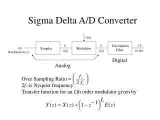
Introduction • Time-interleaved architecture • Two-stage resistor offset averaging gives an ENOB of 3.65 bits.
Introduction Fig.1.Two-stage of averaging resistor networks
Architecture of the ADC Fig. 2. Architecture of the proposed 4-bit flash ADC
Circuit Description 1 Fig. 3. Preamplifier
Circuit Description 2 Fig. 4. The 1st latches
Circuit Description 3 Fig. 5. The 2nd and 3rd latches
Circuit Description 4 Table 1. Binary-Gray-Thermometer code implementation
Circuit Description 5 Fig. 6. The encoder Circuit
Simulation Result Table 2. Comparison of the Performance
Layout Fig. 7. Using a ring path for delivery of the input signal to the preamplifier array
Layout Fig. 8. Layout of the ADC
Advantage of the Proposed ADC • All the signals both in the analog part and the digital part are differential. • Overdrive recovery time limits highest ADC clock frequency. • Meta-stability errors
Conclusion • A non-time-interleaved ADC • With no digital calibration technique • More bits