High-Performance Voltage Regulator Assembly for Motor Control Systems
This assembly includes rectifier, inductor, caps, LM2576T-ADJ, POT, and resistors for precise voltage regulation in motor control systems. The wire setup affects the waveforms, which can be adjusted via R1 POT for varying voltages. Load testing conducted with 10 ohms 50W resistors.

High-Performance Voltage Regulator Assembly for Motor Control Systems
E N D
Presentation Transcript
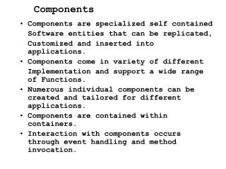
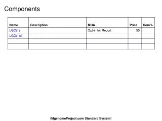
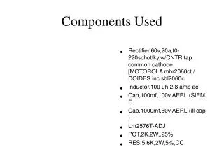
Components Used • Rectifier,60v,20a,t0-220schottky,w/CNTR tap common cathode [MOTOROLA mbr2060ct / DOIDES inc sbl2060c • Inductor,100 uh,2.8 amp ac • Cap,100mf,100v,AERL,(SIEME • Cap,1000mf,50v,AERL,(ill cap ) • Lm2576T-ADJ • POT,2K,2W,.25% • RES,5.6K,2W,5%,CC
Vin 25 V and Vout 20 V • The wave form is measure across the Ground point and Lm2576 Pin 2 • That is before Inductor and Cout.
Make the wire that coming out from Lm2576 Pin2 long enough to go through the donut and got the top wave form. • These double pulse is shown when the longer wire is replaced • Those double pulse go away by replacing shorter wire between Lm2576 Pin 2 and Cout.
With Vin 15 V • Probe Measured across the load • By adjusting R1 pot voltage will vary between 5 to 13 V with 15 V input. • In beginning 10 ohms 50 W load was first used. Then replaced with two 10 ohms 50 W parallel and series with 2 ohm 50W