Download

1 / 19
270 likes | 635 Vues
A Quick Introduction to Failure Modes and Effects Analysis (FMEA). Cherrill Spencer SLAC & ILC Magnet Systems Group 25 th January 2007 weekly meeting. INTRODUCTION to FMEA. Proposed ILC has an 85% overall availability goal

E N D
A Quick Introduction to Failure Modes and Effects Analysis (FMEA) Cherrill Spencer SLAC & ILC Magnet Systems Group 25th January 2007 weekly meeting
INTRODUCTION to FMEA • Proposed ILC has an 85% overall availability goal • So its >13000 electromagnets must be highly reliable or quickly repairable • Reliability engineering must be started as early as the conceptual design stage of a project • ILC engineers will adapt methods of reliability engineering used in industry and military projects • For example: math modeling, reliability block diagrams and Failure Mode and Effects Analysis (FMEA) • A technical design of a magnet must undergo a reliability analysis cycle several times in order to reach its maximum possible reliability • The design must achieve a balance between cost, reliability and magnetic field performance • Start with classic HEP lab quadrupole and power system design with extensive operating history • 1st step: make functional and reliability block diagrams QuickIntro to FMEA Cherrill Spencer
First list the functional scopes of the components of the technical system Magnet System Block Diagram e.g. Power supply provides electricity to magnet e.g. DC Magnet provides a magnetic field in its aperture where beam passes QuickIntro to FMEA Cherrill Spencer
Each box is part of the magnet system with a different function. They are connected- see lines. Later part cannot work if earlier part not working QuickIntro to FMEA Cherrill Spencer
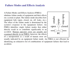
FMEA: Failure Mode and Effects Analysis • FMEA is a structured, qualitative approach to understanding • which components in a system are most likely to fail • what the effects of the failure will be • the root causes of the failure • when in the component’s lifetime it fails • FMEA then obliges you to recommend actions to eliminate or reduce the effect of a failure mode and to follow through taking that action • FMEA was developed by the US military in 1960s • US MIL-STD-1629 • Special worksheet is completed by a team of engineers and other technical personnel with extensive experience on the system being analyzed (example worksheets for DC Magnet below) • FMEA done at design, production and operation phases of a project • MTBF and MTTR data used in FMEA comes from published data ( MIL-HDBK-217, Bellcore Issue 5 etc) or from the team’s operational experience QuickIntro to FMEA Cherrill Spencer
Formation of a FMEA Team • FMEA is most effective when there are inputs into it from all concerned disciplines of the product development team. • However, FMEA is a long process and can become tedious and won’t be effective if too many people participate. An ideal team should have 3 to 4 people from: design, manufacturing, and service departments if possible. • Depending on how complex the system is, the entire process can take anywhere from one to four weeks working full time. QuickIntro to FMEA Cherrill Spencer
FMEA – failure modes & risks • Failure Mode and Effects Analysis (FMEA) is used to assist in identifying potential failure modes early in the process of design of a device. • Traditional FMEA measures risk using the Risk Priority Number (RPN). • The FMEA worksheet consists of a table that will be filled in by the FMEA team, it lists the causes and effects of potential failure modes which are known by the team of engineers. • These failure modes are organized around functions and failures can happen during design, fabrication, measurements, installation or operation. Team decides which phases of life of device they will deal with, don’t have to do all of them at the same time. QuickIntro to FMEA Cherrill Spencer
Components of a FMEA Worksheet Name of component Likelihood this root cause occurs Risk Priority Number = O x S x D Seriousness of the effect Ability of the design controls to detect the failure BEFORE component is released for production QuickIntro to FMEA Cherrill Spencer
Potential Failure Modes • Potential failure mode describes the departure from the intended function or requirement. For function-based FMEA, interpret failure modes as a sub-function occurring improperly or not at all. Potential failure modes can be considered in any of the following four categories: • No Function: There is a complete absence of the intended function. • Partial/degraded function: The item does not meet some of the required functions • Intermittent function: The item performs a function intermittently. • Unintended function: Another function (behavior) is performed which was unintended in the original design. • It is important to note that even if certain failures have never occurred for a similar device, it should be listed on the FMEA worksheet if the failure is physically possible. QuickIntro to FMEA Cherrill Spencer
Occurrence Definition and Table of Values Occurrence is defined as how frequently the specific failure cause is projected to occur during some stated period of time and result in the “failure mode”. A rating table is used to rank the occurrence likelihood. This table below is a possible table for magnet system failures, or we might replace probabilities with failure rates- that come from analyses of failures of real systems of magnets. QuickIntro to FMEA Cherrill Spencer
Severity Definition and Table of Values Severity is typically defined as an assessment of the seriousness of the potential “end effects,” and is assessed independent of the causes. However, we recommend assessing severity based on the entire failure scenario (causes, failure modes and effects). Severity is estimated on a 1 to 10 scale QuickIntro to FMEA Cherrill Spencer
Definition of Detection and Table of Values Detection, sometimes called detectability, has no standard definition. There is some confusion surrounding this index, since different definitions exist for this term. If the team does not have a good understanding of this index, we recommend using a value of “1” for all failures and the team can fill it in later if time permits. The most common interpretation of detection is an assessment of the ability of the “design controls” to identify a potential cause or design weakness before the component, subsystem or system is released for production. Detection scores are generated on the basis of likelihood of detection by the relevant company design review and testing procedures program. QuickIntro to FMEA Cherrill Spencer
Calculate the Risk Priority Number • The Risk Priority Number (RPN) is defined thus: RPN = (Occurrence) (Severity) (Detection) • Larger RPNs indicate the need for corrective action or failure resolution. Max value is 1000. Team needs to decide on a threshold value of RPN for taking action to reduce the risk. • Give special attention to the effect and its causes when the severity rating is high regardless of the RPN. • Note that each discrete failure scenario (i.e. mode, cause, and effect) should have its own associated Occurrence, Severity and Detection values, and therefore a distinct RPN number. QuickIntro to FMEA Cherrill Spencer
Actions Recommended to ReduceRPN • Actions Recommended to ReduceRPN(see worksheet)is a list of corrective actions and failure resolutions. Recommendations could include, in the order of priority: • Design solutions to eliminate the failure mode or reduce its likelihood, including: functional redundancies and error proofing the assembly, installation and usage. • Actions to reduce the severity of the failure mode in terms of its impact on the user, performance, and other systems • Developing means of detecting causes of failure modes during manufacturing including: inspection, testing, and error proofing. • Tests to provide more information data to assess Probability and Severity • Providing diagnostics to easily identify the failure mode or cause during manufacturing or operation. • Establishing periodic maintenance or check-ups to enhance availability and safety. QuickIntro to FMEA Cherrill Spencer
Example of a FMEA Worksheet for a Water-cooled magnet–just a few of the many possible failure modes QuickIntro to FMEA Cherrill Spencer
Problems with traditional FMEA • Ordinal values preserve rank in a group of items, but the distance between the values cannot be measured since a distance function does not exist . • Thus, the product or sum of ordinal variables loses its rank since each parameter has different scales. • The RPN is a product of 3 independent ordinal variables, it can indicate that some failure types are “worse” than others, but give no quantitative indication of their relative effects. • So a cost-based FMEA has been developed- Spencer will be sending out a detailed instruction manual about FMEA and cost-based FMEA QuickIntro to FMEA Cherrill Spencer
Life Cost FMEA of Electromagnet with Monte Carlo Simulation Origin & Detection Legend DR: Design Review Test: QC Inst: Installation TR: Test Run Oper: Operation Determined from Empirical Data Simulated Variables: Detection Time, Fixing Time, Delay Time, Quantity, Parts Cost QuickIntro to FMEA Cherrill Spencer
Benefits of a FMEA Process • Can be started at the conceptual design phase • by dealing with potential reliability problems early, development time can be shortened, costs reduced • Provides engineers witha deep understanding of the structure of a system and the factors that influence reliability • Encourages people from different disciplines to work and problem solve as a team; improves their communications, positively effects the overall engineering enterprise • Assures management that reliability is being properly addressed • Obliges engineers to collect and document their experiences of device failures and repairs in a structured format that others can use later • Moves a project towards the most reliable device designs QuickIntro to FMEA Cherrill Spencer
Useful Aspects of Cost-Based FMEA • Failure risk is measured in terms of expected cost • - Risk is measured in terms of time which translates into cost • - Engineers can compare failure cost with cost of avoiding failure • - Helps compare strategies for improving availability • - Helps compare competing designs by calculating life-cycle costs • for each • Monte Carlo simulation considers uncertainty in failure parameters • - Flaw of averages is avoided • Magnet system can be optimized in terms of: • Failure cost • Availability • Capital cost QuickIntro to FMEA Cherrill Spencer